Fuel injection device

A fuel injection device and fuel injection technology, which are applied in the directions of fuel injection control, combustion engine, internal combustion piston engine, etc., can solve the problems of difficulty in fully reducing soot, and inability to ensure the time for sufficient fuel mixing, and achieve the effect of reducing combustion noise.

Active Publication Date: 2013-11-27
TOYOTA IND CORP
View PDF8 Cites 5 Cited by
  • Summary
  • Abstract
  • Description
  • Claims
  • Application Information

AI Technical Summary

Problems solved by technology

If the advancement of the fuel injection timing is limited to avoid this disadvantage, it will not be possible to secure enough time to mix the air and the increased fuel, and as a result, it will be difficult to sufficiently reduce soot.

Method used


Image

  • Fuel injection device
  • Fuel injection device
  • Fuel injection device

Examples


Embodiment Construction

[0029] Hereinafter, preferred embodiments of the present invention will be described in detail with reference to the drawings.

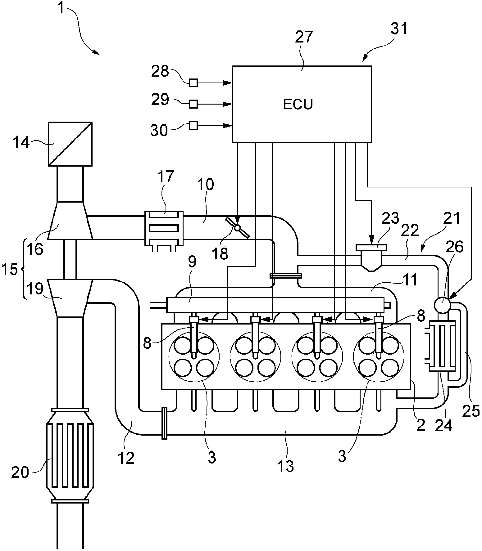
[0030] figure 1 It is a schematic configuration diagram showing a diesel engine including the fuel injection device according to the present embodiment. The diesel engine 1 according to the present embodiment is an inline four-cylinder diesel engine. The diesel engine 1 includes an engine body 2 in which four cylinders 3 are provided.

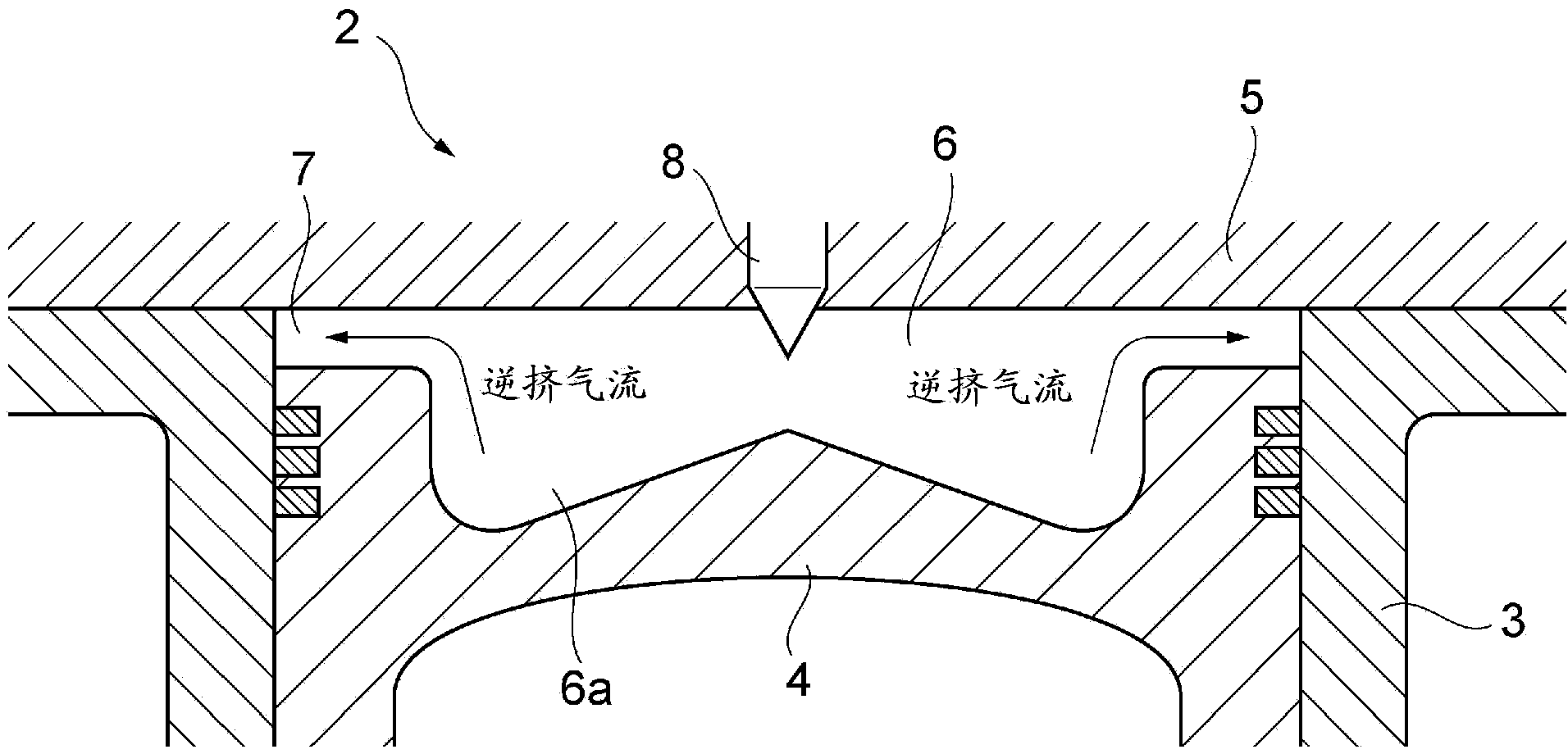
[0031] Such as figure 2 As shown, a piston 4 is accommodated in the cylinder 3 . A cylinder head 5 is disposed above the cylinder 3 . The space surrounded by the cylinder 3 , the piston 4 and the cylinder head 5 constitutes a combustion chamber 6 . A chamber 6 a constituting a part of the combustion chamber 6 is formed at the top of the piston 4 . A region between a portion of the piston 4 on the outer peripheral side of the chamber 6 a and the cylinder head 5 constitutes a squish region 7 .

[0032] Injectors...


PUM


Abstract

This fuel injection device is provided with a fuel injection valve that injects fuel into the combustion chamber of an engine; and an electronic control unit that operates the fuel injection valve in a manner so as to cause the fuel to be injected split into a plurality of instances. The electronic control unit controls the time of a first fuel injection by the fuel injection valve in a manner so that the first fuel injection is performed at the lagging side of the period at which the pre-mixing time immediately after the first injection is minimized, and controls the time of a second fuel injection by the fuel injection valve in a manner so that the heat release rate waveform generated by the first fuel injection and the subsequent second fuel injection is a double-peaked shape.

Description

technical field [0001] The present invention relates to a fuel injection device for an engine performing premixed compression ignition (PCCI: Premixed Charge Compression Ignition) combustion. Background technique [0002] As a conventional fuel injection device, for example, those described in Patent Documents 1 and 2 are known. The fuel injection device described in Patent Document 1 switches the fuel injection mode between the diffusion combustion mode and the premix combustion mode according to the engine load. With this fuel injection device, when the fuel injection mode is switched from the diffusion combustion mode to the premix combustion mode, the oxygen concentration in the combustion chamber is gradually decreased, the fuel injection amount of the pilot injection is gradually increased, and the fuel injection amount of the main injection is gradually increased. The injection amount is gradually reduced, and at the same time, the interval between the pilot injectio...

Claims


Application Information

Patent Timeline
Patent Type & Authority Applications(China)
IPC IPC(8): F02D41/40F02D41/04F02D45/00
CPCF02D41/402Y02T10/44F02D2041/389F02D41/30F02D35/028F02D41/3035Y02T10/12Y02T10/40
Inventor 葛山裕史河合谨町田匡浩滨松健仁
Owner TOYOTA IND CORP
Why Eureka
Try Eureka