
Double-head hand-pressing rotating mop capable of facilitating control of rotation of dewatering basket

A technology of rotating mops and dewatering baskets, which is applied in the directions of carpet cleaning, floor cleaning, cleaning equipment, etc., can solve the problems of increasing the physical burden of users, complex mop bucket structure, cumbersome production process, etc., and achieves simple production, ingenious structure, Practical effect

Active Publication Date: 2013-12-04
浙江美添乐家居用品股份有限公司
View PDF5 Cites 1 Cited by
  • Summary
  • Abstract
  • Description
  • Claims
  • Application Information

AI Technical Summary

Problems solved by technology

[0002] At present, the cleaning and drying of the double-headed mops on the market are all done by stepping on the mop bucket or hand-pulling the rotation mechanism, which makes the structure of the mop bucket complex, not only the production process is cumbersome, but also prone to accidents during use. Fault; In addition, when the rotating mechanism is set on the mop bucket, it is also necessary to set up a matching driving mechanism, that is, a stepping or hand-pulling driving mechanism, which not only increases the weight, but also increases the physical burden of the user

Method used


Image

  • Double-head hand-pressing rotating mop capable of facilitating control of rotation of dewatering basket
  • Double-head hand-pressing rotating mop capable of facilitating control of rotation of dewatering basket
  • Double-head hand-pressing rotating mop capable of facilitating control of rotation of dewatering basket

Examples


Embodiment Construction

[0012] Below in conjunction with accompanying drawing, the present invention is described in further detail:

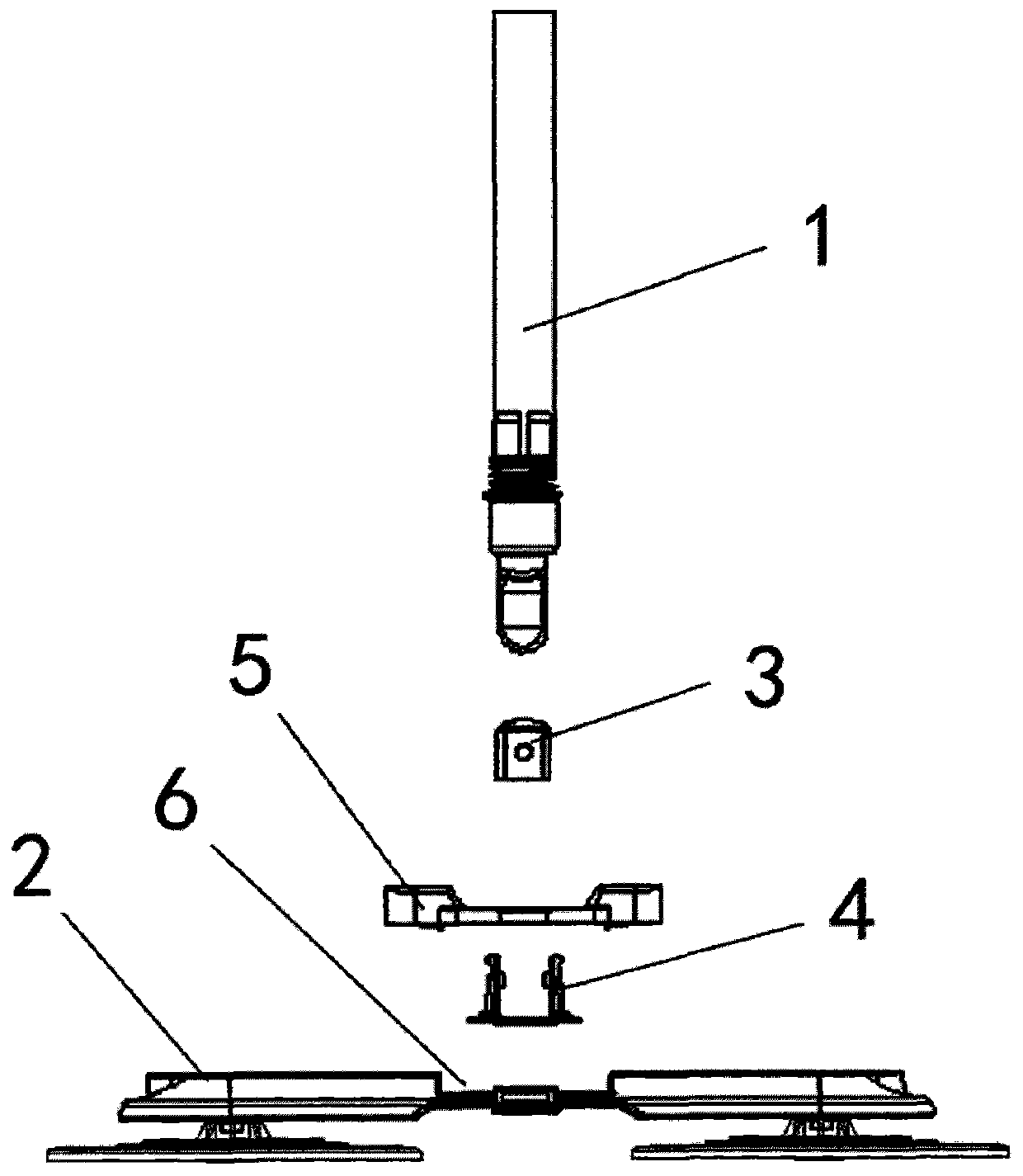
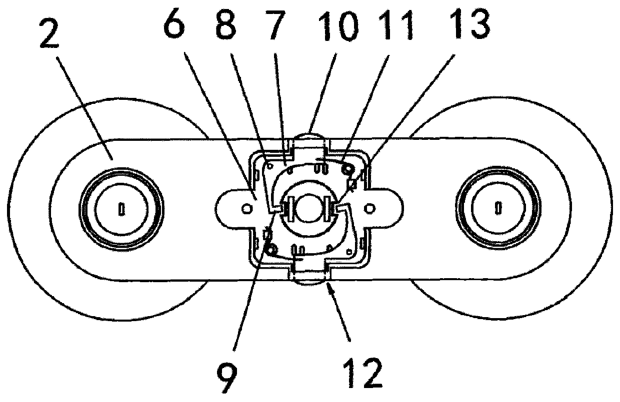
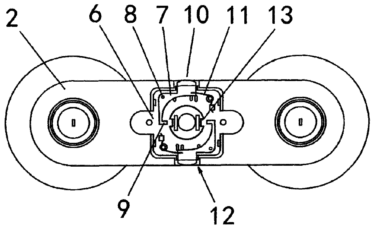
[0013] like figure 1 , figure 2 and image 3 As shown, a double-headed hand-pressed rotary mop that is convenient to control the rotation of the dehydration basket includes a mop rod 1 and a double-headed mop disc 2. The mop rod 1 is connected to a driving sleeve 3, and the driving sleeve 3 is connected to a rotating member 4. The rotating part 4 is fixed on the double-headed mop disc 2 through the clamp 5, and it is characterized in that: the middle part of the double-headed mop disc 2 is provided with a groove 6, and a swing buckle 7 is arranged in the groove 6, and the swing buckle Buckle 7 is right-angled, and the middle part of swing buckle 7 is fixed on the shaft 8. The inside end of swing buckle 7 is provided with latching teeth 9, and the outside end is provided with tongue 10, and the root of tongue 10 is connected with snap spring 11. The part 10 stretch...


PUM


Abstract

The invention discloses a double-head hand-pressing rotating mop capable of facilitating control of rotation of a dewatering basket. The double-head hand-pressing rotating mop comprises a mop rod and a double-head mop disc. The mop rod is connected with a driving sleeve. The driving sleeve is connected with a rotating piece. The rotating piece is fixedly arranged on the double-head mop disc through a clamping piece. The double-head hand-pressing rotating mop is characterized in that a groove is arranged at the middle part of the double-head mop disc, a swinging fastener is arranged in the groove, the middle part of the swinging fastener is fixedly arranged on a shaft, clamping teeth are arranged on the inner side end of the swinging fastener, tongue parts are arranged on the outer side end of the swinging fastener, the roots of the tongue parts are connected with clamping springs, the tongue parts can stretch out of the groove and retract into the groove through holes which are formed in the side walls of the groove, and clamping ports which are engaged with the clamping teeth are formed in the rotating piece. Compared with the prior art, the double-head hand-pressing rotating mop capable of facilitating control of rotation of the dewatering basket has the advantages that the structure is ingenious, the design is reasonable, the practicability is high, the orientation and the direction of the mop disc can be controlled conveniently, the mop can be cleaned more conveniently, the cost is low and the mop is simple to manufacture.

Description

technical field [0001] The invention relates to a mop structure, in particular to a double-head hand-pressed rotary mop which is convenient for controlling the rotation of a dehydration basket, and belongs to the field of daily necessities. Background technique [0002] At present, the cleaning and drying of the double-headed mops on the market are all done by stepping on the mop bucket or hand-pulling the rotation mechanism, which makes the structure of the mop bucket complex, not only the production process is cumbersome, but also prone to accidents during use. Fault; In addition, when the swivel mechanism is set on the mop bucket, it is also necessary to set a supporting drive mechanism, that is, a pedal-type or hand-pulled drive mechanism, which not only increases the weight, but also increases the physical burden of the user. Then, the simple and easy method of rotating the mop rod by hand to drive the dehydration basket has become a key research topic for technical per...

Claims


Application Information

Patent Timeline
IPC IPC(8): A47L13/254A47L13/58
Inventor 周伟明
Owner 浙江美添乐家居用品股份有限公司
Learn More