Bending machine with assisted locating jig

An auxiliary positioning and bending machine technology, applied in the field of bending machines, can solve problems such as torsion deformation, affecting product quality, scratches, etc., and achieve the effect of ensuring bending quality

Inactive Publication Date: 2013-12-04
ENG EQUIP CO LTD SUZHOU SAI SIDE
View PDF8 Cites 2 Cited by
  • Summary
  • Abstract
  • Description
  • Claims
  • Application Information

AI Technical Summary

Problems solved by technology

[0002] The bending of the plate is usually completed by a bending machine. The ordinary bending machine includes the body of the bending machine, the storage area for storing the plate, and the stamping plate that moves up and down through the motor, and the downward pressure of the stamping plate Press the plate into the storage area, which is provided with a notch, so as to complete the bending process of the plate. Generally speaking, after the plate is transported to the bending storage area, the positioning column on the side of the stamping plate will play a certain role in the plate. However, in fact, due to the unevenness of some plates themselves, when the time comes to bend, although there are positioning columns for head positioning, the second half of the plate is still caused by the extrusion force brought by the powerful stamping plate. Torsional deformation, or scratches, affecting product quality

Method used


Image

  • Bending machine with assisted locating jig
  • Bending machine with assisted locating jig

Examples


Embodiment Construction

[0012] The present invention is described in detail below in conjunction with accompanying drawing and specific embodiment:

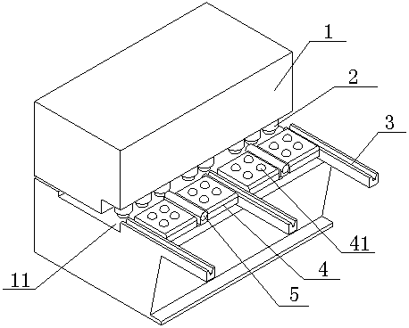
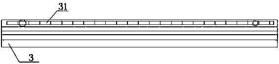
[0013] figure 1 A bending machine with an auxiliary positioning fixture is shown, including a bending machine body 1, on which a workbench 11 for placing plates and a stamping plate for extruding the plates are provided (not shown), a set of positioning columns 2 is also set on one side of the stamping plate, and three guide rods 3 are arranged at equal intervals on the workbench 11, and the guide rods 3 are fixed on the workbench 11 by bolts, A group of anti-deviation mechanisms are arranged between the guide rods 3 .

[0014] Further, the anti-deflection mechanism is composed of a positioning plate 4 and a smooth column 5. There are two positioning plates 4. The smooth column 5 is fixed laterally between the two positioning plates 4. The positioning plate 4 is fixed on the On the workbench 11 , at least one light ball 41 is embedded in the posit...


PUM


Abstract

The invention relates to a bending machine with an assisted locating jig. The bending machine comprises a bending machine body, wherein the bending machine body is provided with a workbench for placing plates and a punching plate for extruding the plates, and one side of the punching plate is also provided with a group of positioning posts. The bending machine is characterized in that three equally spaced guiding rods are arranged on the workbench and are fixedly arranged on the workbench through bolts, a group of anti-deflection mechanism is arranged between every two adjacent guiding rods, each anti-deflection mechanism consists of two positioning plates and a smooth post which is horizontally and fixedly arranged between the two positioning plates, the positioning plates are fixedly arranged on the workbench through bolt bases, at least one smooth ball is embedded into each positioning plate, and the horizontal top end of each smooth post and the topmost end of the corresponding smooth ball are located on the same horizontal surface. The bending machine is used for high-precision bending, advance detection is carried out on the planes where to-be-bent plates are located by means of the anti-deflection mechanisms, head parts of the plates are prevented from deforming due to nonuniform extrusion force when the plates are bent, and the bending quality is ensured.

Description

technical field [0001] The invention relates to a bending machine, in particular to a bending machine with an auxiliary positioning jig which improves the bending quality and ensures that the bending head does not deform. Background technique [0002] The bending of the plate is usually completed by a bending machine. The ordinary bending machine includes the body of the bending machine, the storage area for storing the plate, and the stamping plate that moves up and down through the motor, and the downward pressure of the stamping plate Press the plate into the storage area, which is provided with a notch, so as to complete the bending process of the plate. Generally speaking, after the plate is transported to the bending storage area, the positioning column on the side of the stamping plate will play a certain role in the plate. However, in fact, due to the unevenness of some plates themselves, when the time comes to bend, although there are positioning columns for hea...

Claims


Application Information

Patent Timeline
Patent Type & Authority Applications(China)
IPC IPC(8): B21D5/01B21D43/00
Inventor 顾建强
Owner ENG EQUIP CO LTD SUZHOU SAI SIDE
Why Eureka
Try Eureka