
Hydraulic indexing tool rest

A tool holder and hydraulic technology, applied in the field of machine tool holder, can solve the problems of large positioning impact, difficult position control of induction motor and hydraulic rotary cylinder, slow tool change speed, etc.

Active Publication Date: 2013-12-04
JIANGSU HONGDA NUMERICAL CONTROL TECH CO LTD
View PDF10 Cites 2 Cited by
  • Summary
  • Abstract
  • Description
  • Claims
  • Application Information

AI Technical Summary

Problems solved by technology

[0003] Due to the difficulty in controlling the position of the induction motor and the hydraulic rotary cylinder, at present, the hydraulic tool post generally can only rotate at a fixed angle and cannot be indexed continuously, and the tool change speed is slow and the accuracy of the tool change is not high; the indexing driven by the induction motor The tool holder needs to use a grooved wheel mechanism (such as a machining center tool magazine) or a reverse locking mechanism (such as a CNC lathe tool holder). Going over the positioning point and "rearring" positioning; therefore, in the occasions where the CNC machine tool post, tool magazine, etc. have high requirements for impact and require fast and continuous indexing and positioning, it is generally necessary to use an expensive servo motor to drive the indexing tool post

Method used


Image

  • Hydraulic indexing tool rest

Examples


Embodiment Construction

[0012] In order to make the content of the present invention easier to understand clearly, the present invention will be described in further detail below according to specific embodiments in conjunction with the accompanying drawings,

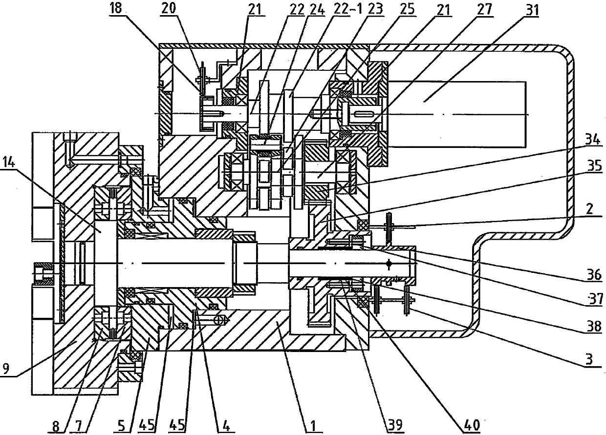
[0013] Such as figure 1 As shown, a hydraulic indexing tool holder, which includes a box body 1, a fixed shaft 14, a cutter head 9, a fixed ring gear 7, a movable ring gear 8, a gear plate connecting plate 5, a piston 4, a hydraulic motor 31, and a driving gear 34. Fixed shaft gear 35, parallel conjugate cam indexing mechanism, signaling wheel 36, cutterhead locking sensor 2, tool position transposition sensor 20, detection wheel 18, multiple tool position sensors 3 and control The control system for the action of the piston 4 and the action of the hydraulic motor 31. The fixed shaft 14 is supported on the box body 1 and can move axially relative to the box body 1. The cutter head 9 is fixedly sleeved on the head end of the fixed shaft 14. The...


PUM


Abstract

The invention discloses a hydraulic indexing tool rest. The hydraulic indexing tool rest comprises a box body, a fixed axle, a cutter, a fixed tooth ring, a movable tooth ring, a tooth disk connecting plate, a piston, a hydraulic motor, a driving gear, a fixed axle gear, a parallel conjugate cam indexing mechanism, a signal sending wheel, a cutter locking sensor, a cutter spacing conversion sensor, a checkout wheel, a cutter sensor and a control system for controlling action of the piston and controlling action of the hydraulic motor, wherein the fixed tooth ring is meshed and matched with the movable tooth ring; the fixed tooth ring is fixedly connected with the tooth disk connecting plate; the movable tooth ring is fixedly connected with the cutter; the driving gear is movably connected with the parallel conjugate cam indexing mechanism; and the hydraulic motor is movably connected with the parallel conjugate cam indexing mechanism so as to drive continuous input motion of the hydraulic motor to be converted into intermittent output motion of the driving gear. According to the hydraulic indexing tool rest, the tool changing speed and tool changing precision can be improved, the cutter is driven to rotate with hydraulic pressure, indexing, loosening and locking actions are smooth, the torque is large and stable, and the hydraulic indexing tool rest is suitable for machine tools for heavy cutting and continuous indexing requirements.

Description

technical field [0001] The invention relates to a hydraulic indexing tool holder, which belongs to the technical field of machine tool holders. Background technique [0002] At present, the indexing tool post is widely used in the rotary positioning of CNC machine tools, tool magazines and other mechanical equipment. In order to reduce manufacturing costs and improve use efficiency, the indexing tool post is preferably driven by an ordinary induction motor or a hydraulic rotary cylinder. And can rotate continuously and index positioning. [0003] Due to the difficulty in controlling the position of the induction motor and the hydraulic rotary cylinder, at present, the hydraulic tool post generally can only rotate at a fixed angle and cannot be indexed continuously, and the tool change speed is slow and the accuracy of the tool change is not high; the indexing driven by the induction motor The tool holder needs to use a grooved wheel mechanism (such as a machining center too...

Claims


Application Information

Patent Timeline
IPC IPC(8): B23B21/00B23Q3/155B23Q16/02
Inventor 陈清锋吴华平
Owner JIANGSU HONGDA NUMERICAL CONTROL TECH CO LTD
Learn More