Thin-wall sleeve inner hole finish machining clamp and inner hole machining method

A thin-walled sleeve, inner hole technology, applied in the direction of manufacturing tools, metal processing equipment, metal processing machinery parts, etc., can solve the problems of high production cost, out of tolerance, easy to deform in clamping and processing, and improve production efficiency and efficiency. Economic benefits, lower production costs, and the effect of avoiding deformation

Inactive Publication Date: 2013-12-04
JIANGXI HONGDU AVIATION IND GRP
View PDF7 Cites 27 Cited by
  • Summary
  • Abstract
  • Description
  • Claims
  • Application Information

AI Technical Summary

Problems solved by technology

[0002] The thin-walled sleeve is a cylindrical part with an external dimension of φ165x60 and a wall thickness of 6mm. The material is No. 45 steel, and the tolerance of the outer diameter and inner hole is 0.025mm. The tube wall of the part is thin and the rigidity is poor. Clamping and processing Easily deformed
In the trial production stage, the technological process of rough turning, heat treatment and tempering, and then finishing is adopted; special attention is paid to the finishing process, the lathe with the best precision is selected, and the processing is performed by experienced masters, but the inner and outer circles of the parts are always out of tolerance by 0.02 More than mm, the scrap rate is almost 100%, and the production efficiency is low, the production cost is high, and there is no market competitiveness

Method used


Image

  • Thin-wall sleeve inner hole finish machining clamp and inner hole machining method

Examples


Embodiment 1

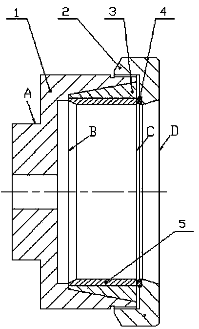
[0013] Example 1 Such as figure 1 Shown: a fixture for finishing the inner hole of a thin-walled sleeve. The positioning seat 1 is composed of a small cylinder A and a large cylinder. The right end of the large cylinder cavity is a conical surface, and the left end of the large cylinder cavity is a round hole. Between the conical surfaces at the right end is a transitional step surface B, and the right end of the large cylinder is provided with a fine-toothed external thread; the external conical surface of the elastic bushing 3 and the right end of the inner cavity of the positioning seat 1 have a taper of 1:10, and the thin-walled sleeve is 5 packs The inner hole of the cylindrical surface of the elastic bushing 3, the left end of the elastic bushing 3 and the thin-walled sleeve 5 withstand the transitional step surface B; The external thread on the right end is matched, and the thin-walled sleeve 5 is compressed by the rubber washer 4 . The side wall of the elastic bushi...

Embodiment 2

[0014] Example 2: A method for finishing the inner hole of a thin-walled sleeve using a jig for finishing the inner hole of the thin-walled sleeve described in Embodiment 1, including:

[0015] ① Fix the small cylinder A of the positioning seat 1 on the three-jaw chuck of the CK63 CNC lathe, and strictly correct the radial and axial runout tolerance of the positioning seat 1 within 0.01mm;

[0016] ② Put the elastic bushing 3 into the inner cavity of the positioning seat 1, and then put it into the thin-walled sleeve 5. The inner hole of the elastic bushing 3 is a cylindrical surface, and maintain a 0.15mm gap with the outer circle of the thin-walled sleeve 5 in the natural state;

[0017] ③ Surface A is concentric with the conical surface, the inner cavity B, C end surfaces and right end surface D are all perpendicular to the axis of surface A, and the outer circle of the right end of positioning seat 1 adopts fine thread, which is also concentric with surface A.

[0018]...


PUM


Abstract

The invention relates to a thin-wall sleeve inner hole finish machining clamp and an inner hole machining method. A locating base is composed of a small cylinder A and a big cylinder in an integrated mode. The right end of an inner cavity of the big cylinder is a circular conical surface. The left end of the inner cavity of the big cylinder is a round hole. A transition step surface B is arranged between the round hole formed in the left end and the circular conical surface at the right end. The right end of the big cylinder is provided with external threads. An outer circular conical surface of an elastic lining and the right end of an inner cavity of the locating base 1 are mutually matched at the taper of 1:10. A thin-wall sleeve is arranged in an elastic lining cylindrical surface inner hole. The elastic lining and the left end of the thin-wall sleeve abut against the transition step surface B. A rubber gasket is installed at the right end of the thin-wall sleeve. Inner threads of an end cap are matched with fine pitch external threads at the right end of the locating base. The thin-wall sleeve is pressed tightly through the rubber gasket. A cut being 2mm is formed in the side wall of the elastic lining. When the thin-wall sleeve inner hole finish machining clamp is applied to the machining of a thin-wall inner hole, the rigidity of the thin-wall sleeve is guaranteed when inner hole fine machining is conducted, deformation generated in the process of clamping and machining is avoided, the product percent of pass reaches over 95%, the production cost is reduced, the production efficiency is improved, and economic benefits are increased.

Description

technical field [0001] The invention relates to a mechanical processing tool, in particular to a jig for finishing the inner hole of a thin-wall sleeve and a method for processing the inner hole. Background technique [0002] The thin-walled sleeve is a cylindrical part with an external dimension of φ165x60 and a wall thickness of 6mm. The material is No. 45 steel, and the tolerance of the outer diameter and inner hole is 0.025mm. The tube wall of the part is thin and the rigidity is poor. Clamping and processing Very easy to deform. In the trial production stage, the technological process of rough turning, heat treatment and tempering, and then finishing is adopted; special attention is paid to the finishing process, the lathe with the best precision is selected, and the processing is performed by experienced masters, but the inner and outer circles of the parts are always out of tolerance by 0.02 More than mm, the scrap rate is almost 100%, and the production efficiency i...

Claims


Application Information

Patent Timeline
Patent Type & Authority Applications(China)
IPC IPC(8): B23Q3/12B23B1/00
Inventor 胡小乐刘晓松周全福
Owner JIANGXI HONGDU AVIATION IND GRP
Why Eureka
Try Eureka