
Stacker crane with tray automatic recycling function

An automatic circulation and palletizer technology, which is applied in the stacking of objects, conveyors, conveyor objects, etc., can solve the problem that automatic palletizers do not have the function of automatic pallet recycling and recovery.

Active Publication Date: 2013-12-04
GUANGXI LIYUANBAO SCI & TECH
View PDF7 Cites 24 Cited by
  • Summary
  • Abstract
  • Description
  • Claims
  • Application Information

AI Technical Summary

Problems solved by technology

[0005] The purpose of the present invention is to solve the defect and deficiency that the existing automatic palletizer does not have the function of automatic recycling of pallets, and to provide an automatic palletizer with the function of automatic recycling of pallets

Method used


Image

  • Stacker crane with tray automatic recycling function
  • Stacker crane with tray automatic recycling function
  • Stacker crane with tray automatic recycling function

Examples


Embodiment 1

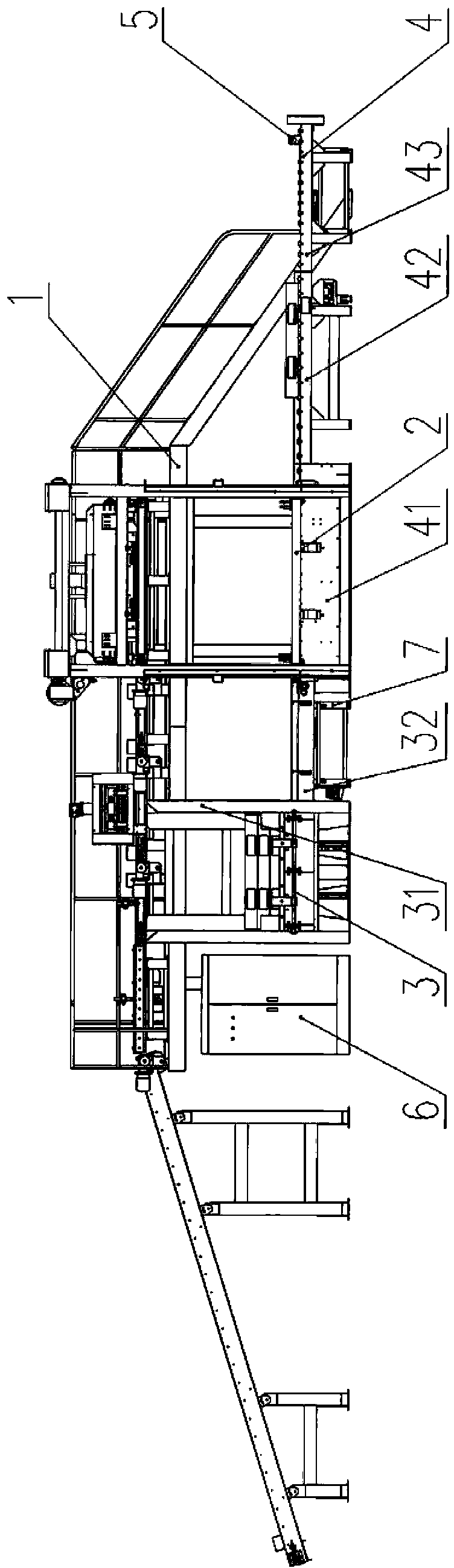
[0036] Such as figure 1 , figure 2 , image 3 , Figure 4 As shown, a kind of palletizer with pallet automatic recycling function in the preferred embodiment of the present invention is mainly composed of elevated platform 1, elevator 2, unpacking machine 3, pallet conveyor 4, sensor 5, electric control cabinet 6, The pallet automatic circulation recovery device 7 is composed of; the lifter 2, the unpacking machine 3, and the pallet conveyor 4 are installed below the elevated platform 1; the pallet unpacking machine 3 is connected in a straight line with the pallet conveyor 4. It can also be connected vertically at 90 degrees; the pallet conveyor 4 is installed under the elevator 2; , the output end of the chain conveyor 32 is linearly connected to the front end of the pallet conveyor 4; the pallet conveyor 4 is the first roller conveyor installed in sequence from the rear end of the chain conveyor 32 of the dismantling machine 3 41. The second roller conveyor 42 and the ...

Embodiment 2

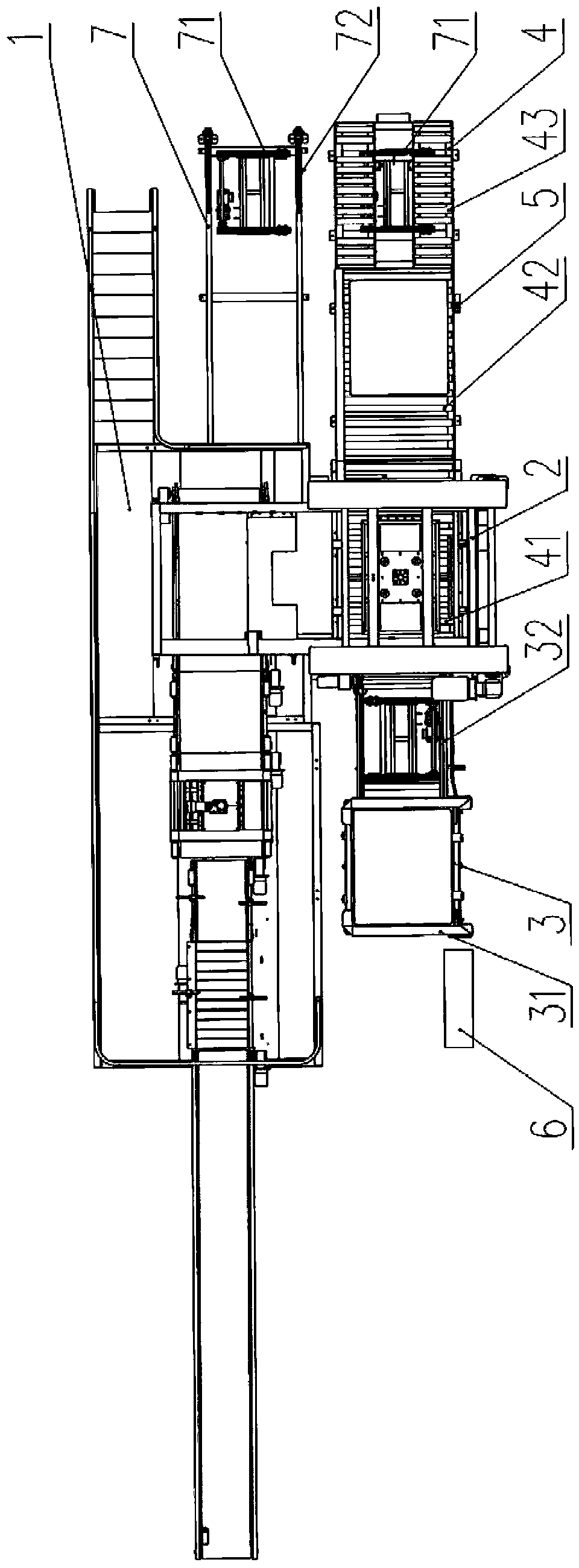
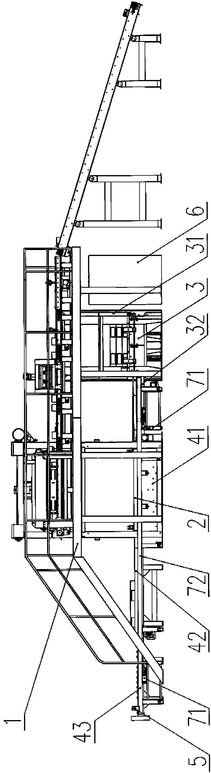
[0039] Such as Figure 5 , Figure 6 , Figure 7 As shown, a kind of palletizer with pallet automatic recycling function in the preferred embodiment of the present invention is mainly composed of elevated platform 1, elevator 2, unpacking machine 3, pallet conveyor 4, sensor 5, electric control cabinet 6, The pallet automatic recycling device 7 is composed of; the palletizer is a high-position double-line automatic palletizer; the lifter 2, the unpacking machine 3, and the pallet conveyor 4 are installed below the elevated platform 1; the palletizing machine 3 It is connected vertically at 90 degrees to the pallet conveyor 4, and in another embodiment, it can also be a straight connection; the pallet conveyor 4 is installed below the elevator 2; Machine 32 is made up of, and chain conveyor 32 is installed in the below of tray storehouse 31, and the output end of chain conveyor 32 is vertically connected on the front end side of pallet conveyor 4; The first roller conveyor 4...


PUM


Abstract

The invention relates to a stacker crane with a tray automatic recycling function. The stacker crane comprises an overhead platform, an elevator, a tray detaching machine, a buttress plate conveyer, a plurality of sensors and an electric control cabinet, wherein the elevator, the tray detaching machine and the buttress plate conveyer are installed below the overhead platform; the tray detaching machine and the buttress plate conveyer are in linear connection or vertical connection; the buttress plate conveyer is installed below the elevator; the tray detaching machine is composed of a tray bin and a chain conveyer installed below the tray bin, and the output end of the chain conveyer is connected to the front end of the buttress plate conveyer in a linear mode; the stacker crane further comprises a tray automatic recycling device installed between the buttress plate conveyer and the tray detaching machine, after stacking is completed, empty trays can be automatically recycled from the tail end of the buttress plate conveyer into the tray bin of the tray detaching machine or into a stacking waiting station between the tray detaching machine and the elevator, and manual handling or forklift handling is not required for recycling.

Description

technical field [0001] The invention belongs to the field of palletizing equipment, and in particular relates to a palletizing machine with the function of automatic recycling of pallets. Background technique [0002] In the production of modern chemical, food, feed, fertilizer and other industries, automatic palletizers have been increasingly used in the automatic palletizing of bagged products. When the automatic palletizer performs palletizing operations, one way is to directly stack the bagged products on the empty pallet, and then transport and store it with the pallet; one way is to spread the binding belt on the empty pallet before palletizing. Then put the bagged products on the bundles. After the palletizing is completed, the bagged products are only carried away with the straps, and the empty pallets left on the pallet conveyor are transported back to the pallet warehouse of the unpacking machine by hand or forklift or disassembled. The stacking between the disc m...

Claims


Application Information

Patent Timeline
Patent Type & Authority Applications(China)
IPC IPC(8): B65G37/00B65G43/08B65G47/52B65G47/90B65G57/00
Inventor 邓秀泉王仲键
Owner GUANGXI LIYUANBAO SCI & TECH
Features
  • Generate Ideas
  • Intellectual Property
  • Life Sciences
  • Materials
  • Tech Scout
  • Unparalleled Data Quality
  • Higher Quality Content
  • 60% Fewer Hallucinations
Learn More