Thread clamping adjustment knob of sewing machine

A sewing machine and knob technology, which is applied to sewing machine components, sewing equipment, tension devices, etc., can solve the problems of increased manufacturing cost, screw damage, and small size of positioning buttons and other components.

Inactive Publication Date: 2013-12-04
顾飞龙
View PDF5 Cites 0 Cited by
  • Summary
  • Abstract
  • Description
  • Claims
  • Application Information

AI Technical Summary

Problems solved by technology

[0004] Because the sewing machine will vibrate under high-speed operation, in order to increase the fixity between the knob and the screw, and prevent the knob from loosening and screwing back and affecting the tension of the sewing thread, the user generally expands the long groove on the end of the screw to increase the diameter of the screw. In order to further increase the screw tightening force between the screw and the screw hole of the knob, and the ratchet part meshes between the positioning knob and the knob to prevent the knob from loosening and screwing back. If it is found that the knob and the screw will gradually loosen, and In order to further increase the screw tightening force between the two, the user will stretch the long groove of the screw rod again. In such a vicious cycle, when the long groove is repeatedly stretched

Method used


Image

  • Thread clamping adjustment knob of sewing machine
  • Thread clamping adjustment knob of sewing machine
  • Thread clamping adjustment knob of sewing machine

Examples


Embodiment Construction

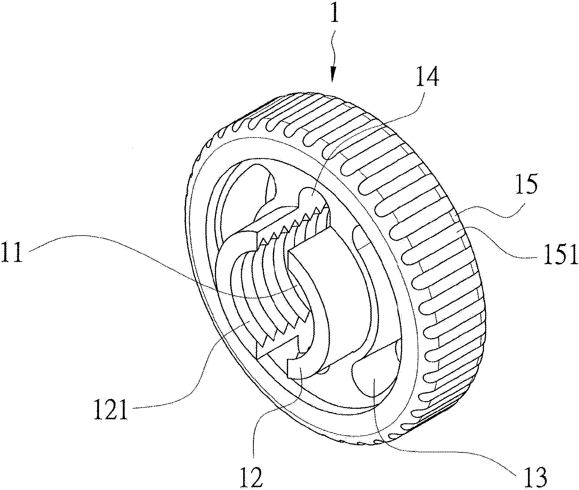
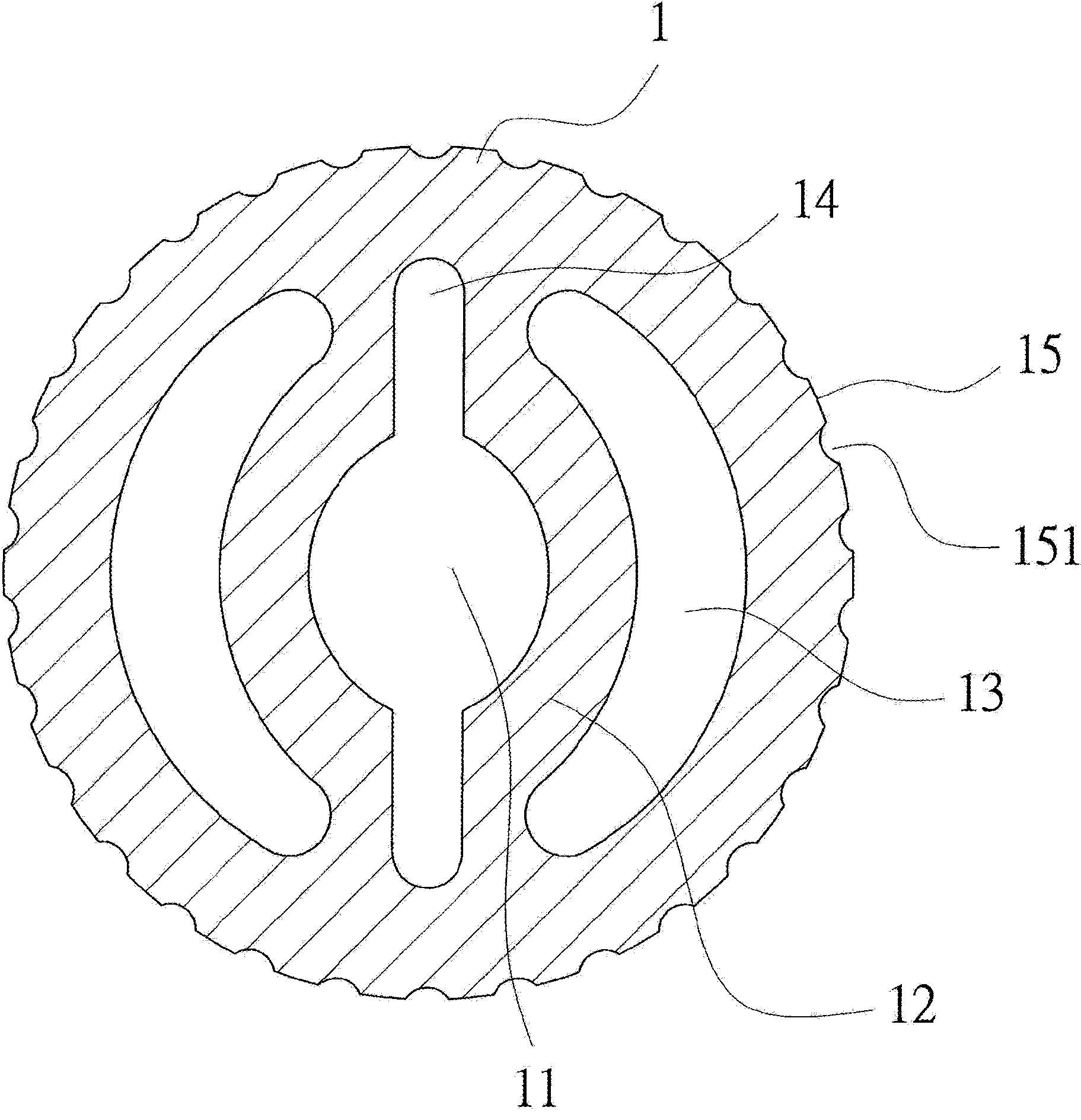
[0030] First, see figure 1 The three-dimensional structure diagram of the present invention shown and figure 2 As shown in the cross-sectional structure diagram of the present invention, the present invention is mainly provided with a knob 1 which is provided with a screw portion 12 formed around and surrounded by the corresponding central through hole 11, and the screw portion 12 corresponds to The inner surface of the through hole 11 is provided with a thread 121, and the outer periphery of the screw portion 12 is provided with an elastic slot 13; a slot 14 is formed between the two screw portions 12, and is formed on the surface of the outer ring portion 15 on the outer edge of the knob 1. There is a recess 151.

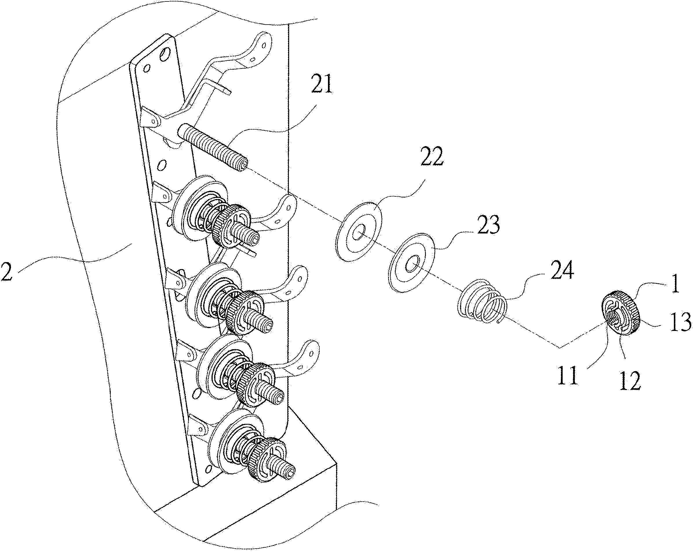
[0031] Therefore, please refer to the operation and use of the present invention image 3 As shown in the three-dimensional exploded state diagram of the present invention, the screw 21 of the sewing machine table 2 can be respectively sheathed with an inner clip 22...


PUM


Abstract

The invention relates to a thread clamping adjustment knob of a sewing machine. The thread clamping adjustment knob of the sewing machine is mainly characterized in that a knob body is arranged on a screw of a sewing machine body in a screwed manner, the knob body is provided with screwing portions which are corresponding to the periphery of a central through hole and formed by surrounding the through hole, the internal diameter of the through hole is smaller than the external diameter of the screw, a thread is arranged on the inner face, corresponding to the through hole, of each screwing portion, and an elastic slot is formed in the periphery of each screwing portion. Thereby, via the elastic through hole, the knob body enables the knob through hole with the diameter smaller than that of the screw to generate extension margin, and screw joint with the screw is benefited, the screw can be clamped tightly to be prevented from loosening due to vibration, the screw can be no longer processed additionally to form an elongated slot, and structural strength of the screw is not damaged; meanwhile, processing cost and time of the elongated slot are reduced, substantial benefits such as simplification of parts and reduction of manufacturing cost are achieved, and practicality and convenience are improved in whole application and use of the knob.

Description

Technical field [0001] The present invention relates to a thread clamping adjustment knob of a sewing machine, in particular to a method that allows the knob to generate expansion and contraction margin, which is beneficial to screw connection with a screw, avoids vibration loosening, and makes the screw no longer need to be processed to form a long groove, reducing Processing cost and time can achieve substantial benefits such as simplifying parts and reducing manufacturing costs, and the overall implementation of the sewing machine thread clamping adjustment knob is more practical and functional. Background technique [0002] Usually, there are several adjustment knobs on the sewing machine to adjust the tightness of the sewing thread; among them, please refer to Figure 7 As shown in the conventional three-dimensional exploded structure diagram, the adjusting knob 3 is mainly provided with a screw 32 protruding from the base 31, a long groove 321 is axially opened in the center ...

Claims


Application Information

Patent Timeline
IPC IPC(8): D05B47/04
Inventor 顾飞龙
Owner 顾飞龙
Why Eureka
Try Eureka