Improved structure of fixed type louver blade outer frame

An improved structure, fixed technology, applied in special equipment for doors/windows, windows/doors, building components, etc., can solve the problems of affecting functions, bending and deformation of outer frame blades, inconvenient construction and use, etc., to facilitate drainage. , Avoid extrusion damage, improve the effect of waterproof effect

Inactive Publication Date: 2013-12-04
LEAD-FU IND CORP
View PDF4 Cites 3 Cited by
  • Summary
  • Abstract
  • Description
  • Claims
  • Application Information

AI Technical Summary

Problems solved by technology

[0003] For the existing "modularized shutter system", please refer to the first, second and third diagrams, which include a peripheral frame a with a bottom sill a1, a rubber head a2 and a pair of side bars a3 to form a rectangular original opening ; Several intermediate structural components a4 combined with the peripheral frame separate the original opening into multiple rectangular modular unit openings; a louver module b receives at least one unit opening, and a viewing screen c, which is fixed on the frame a and covers it firmly In the entire original opening, and the bottom sill a1 of the peripheral frame a is groove-shaped to delineate a water collection area and drainage channel for the louver module b on it to catch water, and its side stiles a3 are tubular and guide For water flow, the horizontal intermediate frame member a4 connects one of the side stiles a3 at the joint, and the joint of the side stile a3 has a drainage hole a31 open to the drainage channel to accommodate the water flowing from the drainage channel through the water channel, and its louver module b has Specific water removal characteristics, and the visual curtain c can also have basic water-re

Method used


Image

  • Improved structure of fixed type louver blade outer frame
  • Improved structure of fixed type louver blade outer frame
  • Improved structure of fixed type louver blade outer frame

Examples


Embodiment Construction

[0032] The embodiment of the improved structure of the fixed window blade outer frame of the present invention will be described in detail below with reference to the accompanying drawings. However, the present invention is not limited to the following examples.

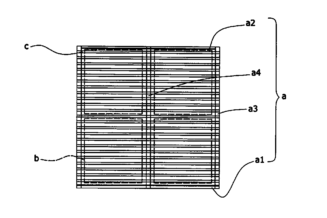
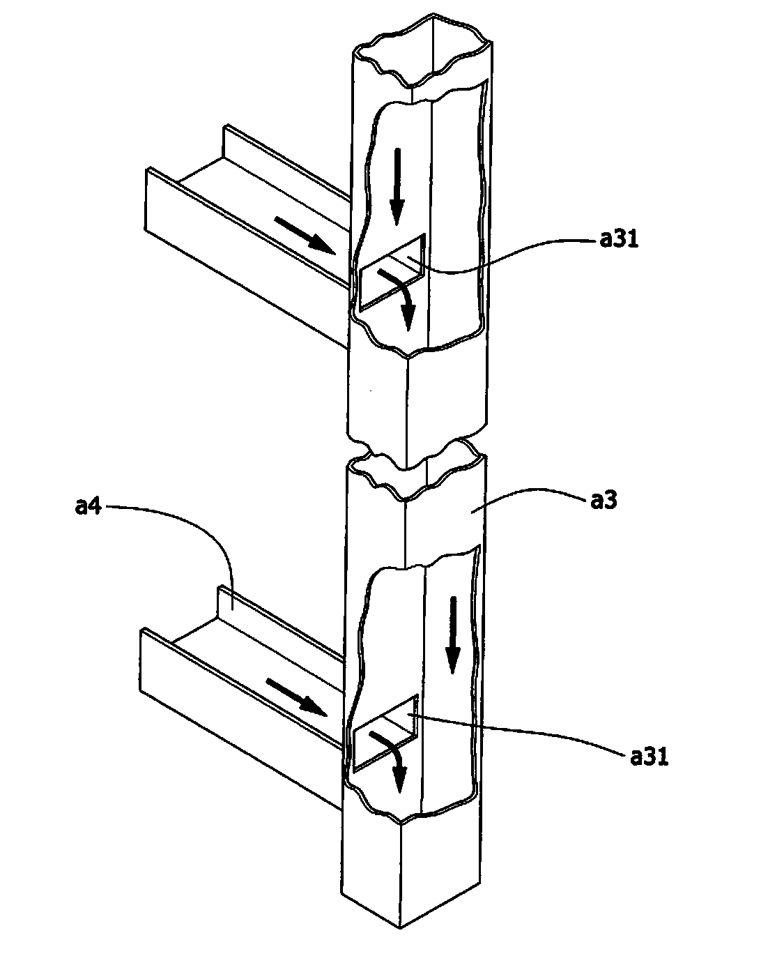
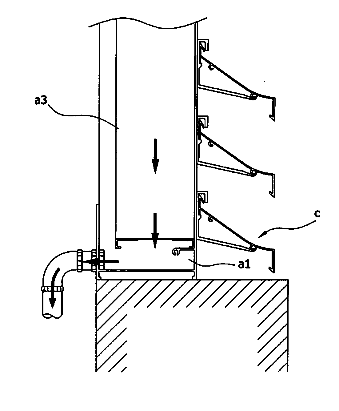
[0033]An improved structure of the outer frame of a fixed window leaf according to the present invention includes a set of fixed window leaves 10, a set of outer frames 20, a plurality of water baffles 30 and a plurality of fixing seats 40, the group of outer frames and The group of fixed window blades is matched and connected on the peripheral surface of the group of fixed window blades, the group of fixed window blades includes a plurality of blades 11 and a pair of inner frames 12, and the plurality of blades are sequentially arranged at intervals Between the pair of inner frames; the group of outer frames includes an upper outer frame 21, a lower outer frame 22, and a pair of upright outer frames 23, and the uppe...


PUM


Abstract

The invention discloses an improved structure of a fixed type louver blade outer frame. The improved structure comprises a set of fixed type louver blades, a set of outer frame bodies, a plurality of water fenders and fixing bases. The blades in the fixed type louver blade outer frame are arranged between a pair of inner frame bodies in an equidistant-interval mode, the upper outer frame body and the lower outer frame body are fixedly connected with the corresponding inner frame bodies respectively in a clamped mode, an admissible space is formed between the upper outer frame body and the corresponding inner frame body, and squeezing damage to the outer frame bodies can be effectively avoided. The pair of up-right outer frame bodies are connected to the two side faces of a non-connecting inner frame body of each fixed type louver blade respectively, gaps are formed between the up-right outer frame bodies and the side faces respectively, and water draining is facilitated. In addition, the fixing bases are arranged on the opposite side edges of each up-right outer frame body in an equidistant-interval mode, the fixing bases on the side edge of each up-right outer frame body correspond to the fixing bases of the side edge of the other up-right outer frame body respectively in a one-to-one mode, each water fender is fixedly connected between one pair of oppositely-arranged fixing bases in a clamped mode, and the water-proof efficacy is greatly improved.

Description

technical field [0001] The invention relates to the technical field of a fixed window blade outer frame, and specifically provides an improved structure of a fixed window blade outer frame. Background technique [0002] Existing general shutters are widely used on the exterior walls of commercial buildings, industrial buildings or public buildings because they can provide various purposes. In addition to the good purpose, the second is to have good waterproof and drainage effects, so as to avoid equipment damage caused by a large amount of rainwater inflow when it rains; [0003] For the existing "modularized shutter system", please refer to the first, second and third diagrams, which include a peripheral frame a with a bottom sill a1, a rubber head a2 and a pair of side bars a3 to form a rectangular original opening ; Several intermediate structural components a4 combined with the peripheral frame separate the original opening into multiple rectangular modular unit opening...

Claims


Application Information

Patent Timeline
IPC IPC(8): E06B7/086
Inventor 苏景棠
Owner LEAD-FU IND CORP
Why Eureka
Try Eureka