Automotive hydraulic vane pump motor and switching control hydraulic system thereof

A technology of a hydraulic system and a vane pump, applied in the field of hydraulic pumps, can solve the problems of complex structure of the pump motor, difficult switching, difficult control, etc., and achieve the effects of avoiding the reduction of volumetric efficiency, simple structure and flexible vane control.

Inactive Publication Date: 2013-12-04
胡阳
View PDF6 Cites 9 Cited by
  • Summary
  • Abstract
  • Description
  • Claims
  • Application Information

AI Technical Summary

Problems solved by technology

This invention can recover the braking energy of the vehicle when the vehicle is braking, but the structure is complicated and the control is difficult. One of the reasons for this situation is that the structure of the pump motor used is relatively complicated, and the difference between the two states of the pump and the motor is relatively complicated. It is not easy to control the switching between them, and the second is that when the vehicle is running normally, the transmission connection with the brake shaft of the vehicle must be disconnected.

Method used


Image

  • Automotive hydraulic vane pump motor and switching control hydraulic system thereof
  • Automotive hydraulic vane pump motor and switching control hydraulic system thereof
  • Automotive hydraulic vane pump motor and switching control hydraulic system thereof

Examples


Embodiment 1

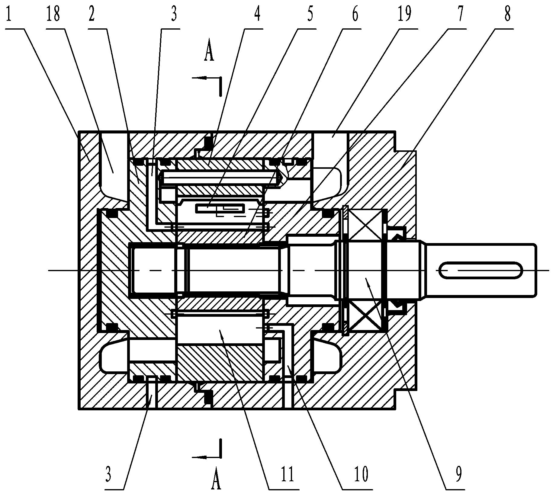
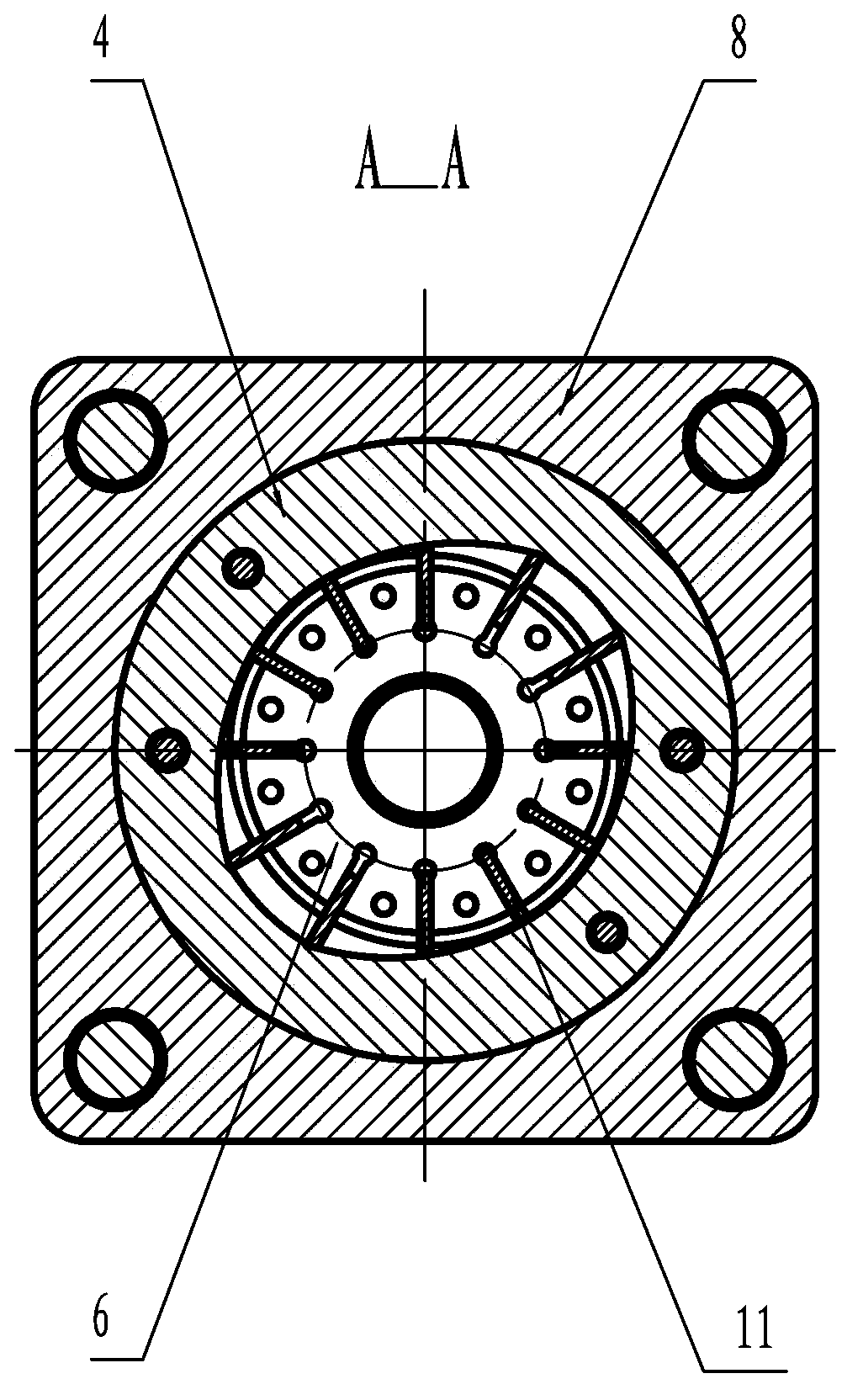
[0025] Embodiment 1: Vehicle hydraulic vane pump motor, as attached figure 1 , attached figure 2 , attached image 3 , attached Figure 4 , attached Figure 5 As shown, it includes rear pump cover 1, oil inlet oil distribution plate 2, stator 4, rotor 6, oil outlet oil distribution plate 7, front pump cover 8, shaft 9, blade 11, oil inlet 19 and oil outlet 18 .

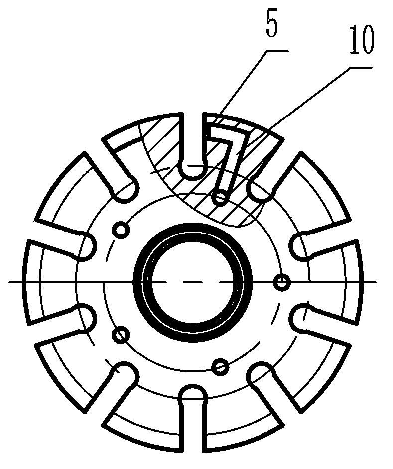
[0026] A hydrostatic oil chamber 5 is provided on the side wall of the vane groove on the rotor 6, and the hydrostatic oil chamber 5 communicates with an external hydraulic source through a signal oil channel 10; When extended to the maximum position and the minimum position, the openings of the static pressure oil chamber 5 are all facing the body of the blade 11 . The hydrostatic oil chamber 5 is an elongated groove, and the distances between the two ends of the groove and the side walls of the corresponding rotor 6 are equal.

[0027] The signal oil channel 10 is a three-stage structure, the first section is...


PUM


Abstract

The invention relates to an automotive hydraulic vane pump motor and a switching control hydraulic system thereof. The pump motor comprises a rear pump cover, an oil-in distribution disc, a stator, a rotor, an oil-out distribution disc, a front pump cover, a shaft, a vane, an oil inlet and an oil outlet, wherein a static pressure oil chamber is formed in one side wall of a vane slot in the rotor and is communicated with an external hydraulic source through a signal oil passage; the static pressure oil chamber takes the shape of a groove and has openings which directly face the body of the vane when the vane extends to the maximal position and the minimal position; a vane root oil chamber, which is used for supplying hydraulic pressure to actuate the vane to extend out, is arranged at the root of the vane; an external switching control hydraulic system is used for supplying hydraulic oil to the vane root oil chamber; the switching control hydraulic system comprises an accumulator, a three-position electromagnetic directional valve and a reversing valve; one oil port in an output end of the reversing valve is communicated with the static pressure oil chamber, and the other oil port is connected with the vane root oil chamber; the oil port in an input end of the reversing valve is connected with signal oil, and a non-return valve is arranged on the accessed oil passage; oil ports in the output end of the three-position electromagnetic directional valve are respectively connected with the oil inlet and the oil outlet, and oil ports in the input end of the three-position electromagnetic directional valve are respectively connected with an oil tank and the accumulator.

Description

[0001] technical field [0002] The invention relates to a hydraulic pump, in particular to a vehicle hydraulic vane pump motor and a switching control hydraulic system thereof. [0003] Background technique [0004] For vehicle braking kinetic energy regeneration, the pump motor is generally used on the vehicle. When the kinetic energy of the vehicle is used for braking or deceleration, the pump motor is used as a pump to pump high-pressure oil into the accumulator to convert the kinetic energy into hydraulic energy. Stored; when the vehicle is starting or accelerating, the pump motor is used as a motor, and the high-pressure oil in the accumulator is used to drive the motor to rotate, driving the vehicle to start and accelerate, reducing the fuel consumption and exhaust emissions of the vehicle; and when the vehicle When driving at a constant speed, the pump motor does not need to work, because as long as there is oil circulation, there will be energy loss. If the pump mo...

Claims


Application Information

Patent Timeline
Patent Type & Authority Applications(China)
IPC IPC(8): F04C2/344F04C15/00F15B1/02F03C2/30
Inventor 陈伟娟胡阳
Owner 胡阳
Why Eureka
Try Eureka