Direct injection valve structure in gas cylinder

An injection valve and gas cylinder technology, applied in the direction of internal combustion piston engine, charging system, combustion engine, etc., can solve problems such as volumetric efficiency loss, and achieve the effect of solving volumetric efficiency loss, high load, and large injection cone angle

Active Publication Date: 2022-05-31
NANYUE FUEL INJECTION SYST CO LTD
View PDF5 Cites 0 Cited by
  • Summary
  • Abstract
  • Description
  • Claims
  • Application Information

AI Technical Summary

Problems solved by technology

At the same time, the loss of volumetric efficiency caused by the gas replacement air caused by the PFI injection method can also be solved

Method used


Image

  • Direct injection valve structure in gas cylinder
  • Direct injection valve structure in gas cylinder
  • Direct injection valve structure in gas cylinder

Examples


Embodiment Construction

[0029] Structure of the present invention, further concrete description is as follows in conjunction with accompanying drawing:

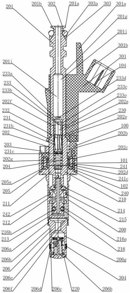
[0030] see Figure 1 to Figure 7 , the gas in-cylinder direct injection valve structure shown in the figure includes: electromagnet component assembly 100, nozzle component assembly 200, and the specific technical scheme is as follows:

[0031] The nozzle part assembly 200 includes: an air inlet joint part, a nozzle body part 240 and an injection valve part 220 .

[0032] The intake joint part includes an intake joint 201, an iron core 202 and an intake valve assembly 230. An air intake hole axially penetrating the entire intake joint 201 is arranged in the intake joint 201, and a second A rod segment 201g, a first hole segment 201i is provided at the lower part of the air intake hole.

[0033] The iron core 202 is made of a magnetically permeable material, and its outer circumference is sequentially provided with a second rod segment 202a, a thir...


PUM


Abstract

The invention discloses an injection valve structure for direct injection in a gas cylinder, which comprises an electromagnet component assembly and a nozzle component assembly, and the nozzle component assembly comprises a gas inlet joint component, a nozzle body component and an injection valve component; the top of the injection valve component is fixed to the bottom of the nozzle body assembly. The air inlet connector component comprises an air inlet connector, an iron core and an air inlet valve assembly, wherein the air inlet connector and the iron core are connected with each other, and the air inlet valve assembly is arranged in an air inlet hole of the air inlet connector and an iron core inner hole of the iron core. The nozzle body component comprises a nozzle body and a balance valve assembly, the top of the nozzle body is connected with the bottom of the air inlet connector through an electromagnet component, and the top of the injection valve component is fixed to the bottom of the nozzle body. A nozzle body inner hole penetrating through the whole nozzle body is axially formed in the nozzle body, and the balance valve assembly is installed in the nozzle body inner hole. A balance valve structure is adopted, and under the same flow area, larger injection pressure can be adopted, and larger gas flow can be obtained.

Description

technical field [0001] The invention belongs to the field of gas injection valves, in particular to a gas in-cylinder direct injection injection valve structure. Background technique [0002] Gas injection valve is a key executive component in the gas supply system of a gas engine, and its performance has a significant impact on injection characteristics such as injection timing, injection duration, and injection mass flow rate. At present, the gas supply strategy widely used in hydrogen internal combustion engines is port injection. Due to the low minimum ignition energy and quenching distance of gas, this injection method may cause problems such as pre-ignition, knocking and flashback. On the other hand, hydrogen displaces air in the intake, limiting the power density of the engine. Contents of the invention [0003] The object of the present invention is to solve the problems existing in the above-mentioned existing products of the same kind, and develop a new gas in-c...

Claims


Application Information

Patent Timeline
Patent Type & Authority Applications(China)
IPC IPC(8): F02M21/02
CPCF02M21/0269F02M21/026F02M21/0275F02M21/0227F02M21/0206Y02T10/30
Inventor 黄民备何静邓飞欧阳玲湘龙美彪伍新义李成校
Owner NANYUE FUEL INJECTION SYST CO LTD
Why Eureka
Try Eureka