an intake pre-swirler

An air intake pre-swirler and pre-swirler technology, which is applied to machines/engines, components of pumping devices for elastic fluids, non-variable-capacity pumps, etc., can solve the design difficulty and adjustment of flow control control systems The blade opening cannot be zero, flow deviation and other problems, so as to avoid energy loss, improve stiffness, and improve work efficiency.

Active Publication Date: 2016-03-02
苏州欧拉透平机械有限公司
View PDF6 Cites 0 Cited by
  • Summary
  • Abstract
  • Description
  • Claims
  • Application Information

AI Technical Summary

Problems solved by technology

At present, the double-suction fan with large flow rate is usually adjusted by a hydraulic coupling, or by installing an adjustment door in front of its air inlet, which will cause a large energy loss
[0003]In addition, in the prior art, most of the air intake pre-rotation devices used as regulating valves are integrated devices, and the regulating blades are basically single-supported, resulting in its The rigidity is poor, and it is easy to deform when the airflow impacts, causing the opening of the pre-rotation device to adjust the vane to be zero when it is closed, and there is also a deviation in the flow rate at a certain opening, which causes certain difficulties in the design of the control system for flow control.

Method used


Image

  • an intake pre-swirler
  • an intake pre-swirler
  • an intake pre-swirler

Examples


Embodiment Construction

[0018] The technical scheme of the present invention will be further described below in conjunction with the accompanying drawings and preferred embodiments of the present invention.

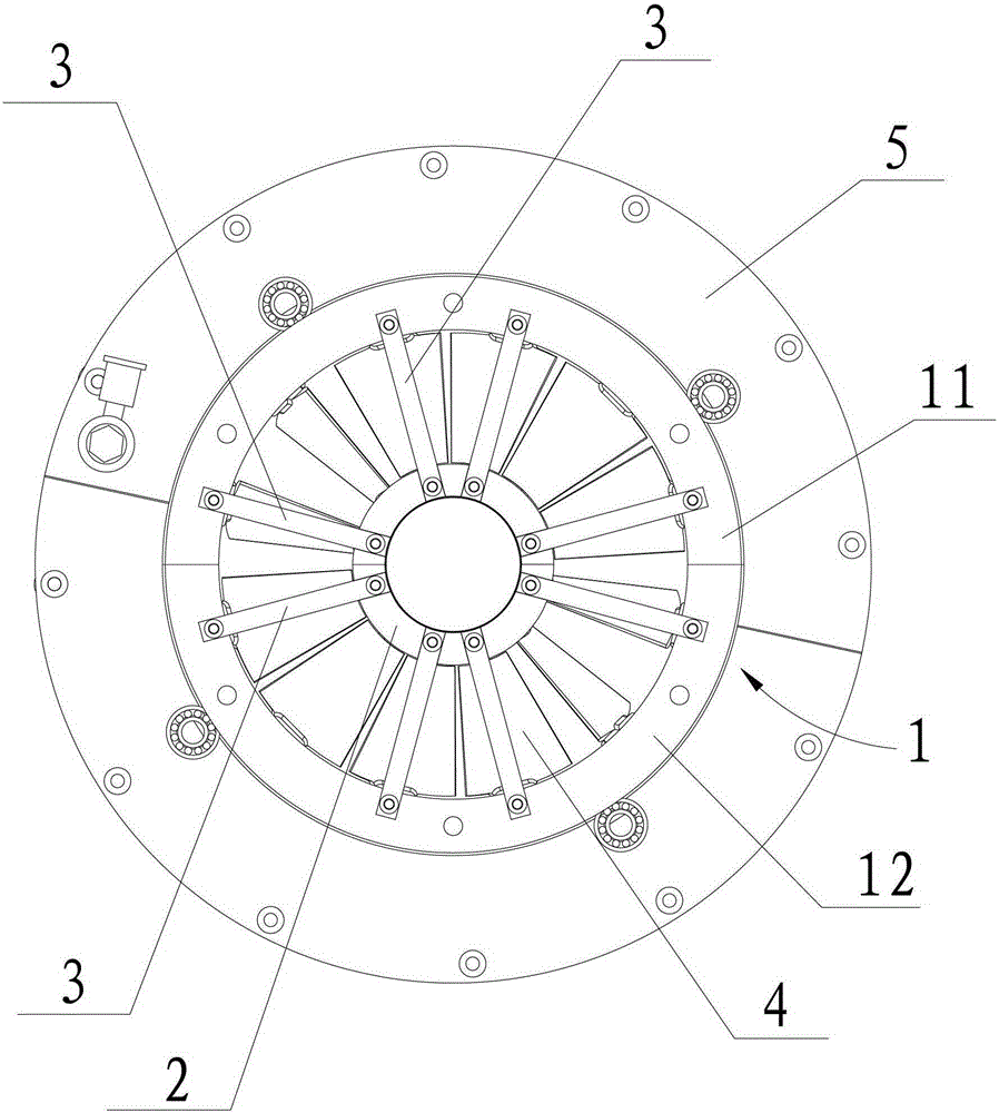
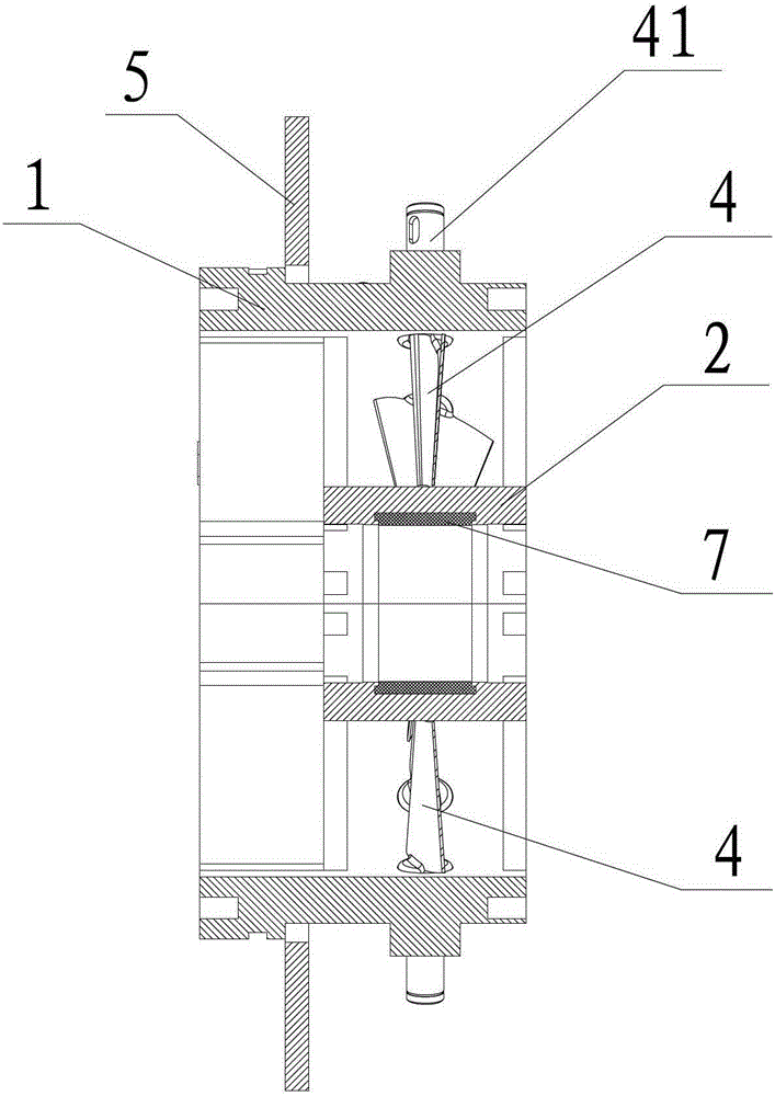
[0019] see Figure 1~4 The air intake pre-rotator shown in the figure includes a fixed outer ring 1 and a fixed inner ring 2. The fixed outer ring 1 has a hollow inner cavity and its two axial ends pass through each other. The two axial ends of the fixed outer ring 1 The ends are respectively used as the air inlet and the air outlet of the pre-rotator. The two shaft ends of the fixed inner ring 2 are sealed. The fixed inner ring 2 is coaxially arranged in the inner cavity of the fixed outer ring 1. The fixed inner ring 2 and the fixed outer ring 1 are fixedly connected by a plurality of connecting rods 3. The multiple The connecting rods 3 are distributed in the circumferential direction of the fixed outer ring 1 and the fixed inner ring 2 at intervals.

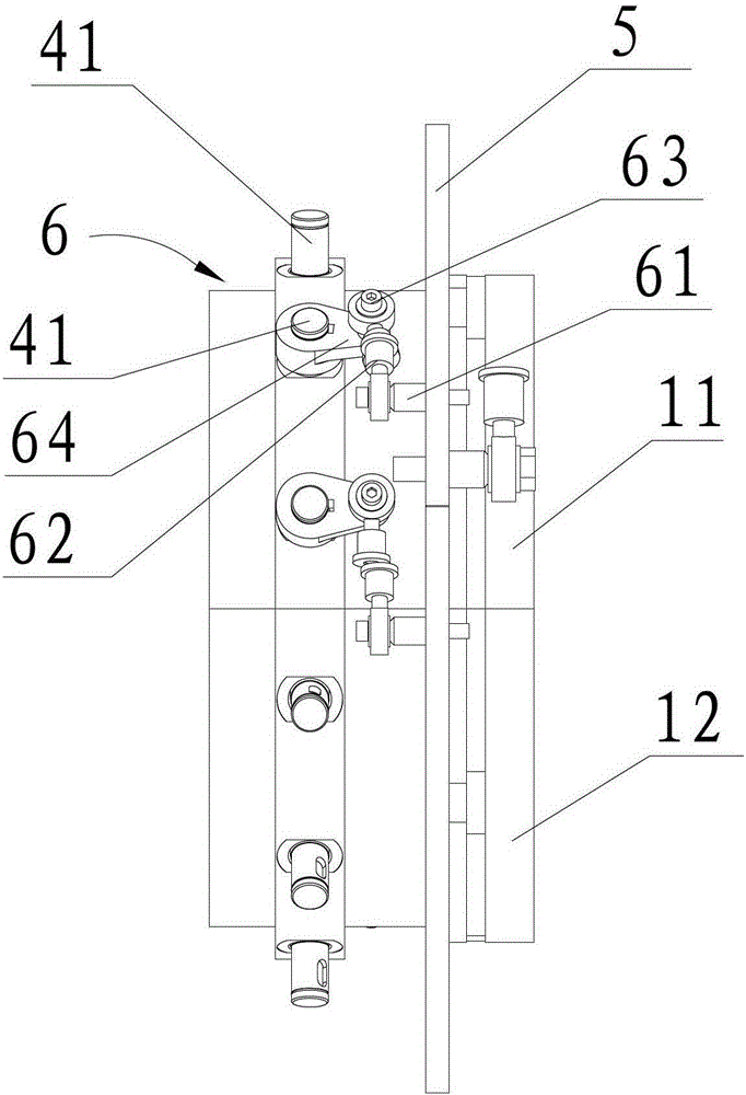
[0020] see Figure 1~4 As shown, the ...


PUM


Abstract

The invention discloses An air intake pre-rotator, comprising a fixed outer ring and a fixed inner ring arranged coaxially, a plurality of connecting rods for connecting the fixed outer ring and the fixed inner ring, and two ends of the fixed outer ring and the fixed inner ring are respectively rotatably arranged on the fixed outer ring and the fixed inner ring. The guide vane on the fixed inner ring, the rotating ring sleeved on the outer circumference of the fixed outer ring, and the driving mechanism for driving the guide vane to rotate. There will be no deformation when the airflow impacts, which makes the opening of the vane on the guide vane easier to adjust and has high adjustment accuracy, so that the flow adjustment of the pre-rotator is more accurate, which ensures that the vane on the guide vane is in the actual opening. The consistency between the flow rate and the design value can provide accurate data for the control system, avoiding the energy loss during flow adjustment in the prior art, and the working efficiency of the fan installed with the pre-rotator will be greatly improved.

Description

technical field [0001] The invention relates to an intake prerotator. Background technique [0002] With the rapid development of the national economy, the application of blowers and compressors is becoming more and more extensive. In order to make the blower and compressor meet the design concept of high efficiency and energy saving under variable working conditions, they must be adjusted reasonably. At present, the double-suction fan with large flow is usually adjusted by a hydraulic coupling, or by installing an adjustment door in front of the air inlet, which will cause a large energy loss. [0003] In addition, in the prior art, most of the air intake pre-swirl devices used as regulating doors are integrated devices, and the regulating blades are basically single-supported, resulting in poor rigidity and easy deformation when the airflow impacts, resulting in pre-swirling The opening of the regulating blade of the device cannot be zero when it is closed, and there is ...

Claims


Application Information

Patent Timeline
Patent Type & Authority Patents(China)
IPC IPC(8): F04D29/38
Inventor 刘廷召金鼎铭
Owner 苏州欧拉透平机械有限公司
Why Eureka
Try Eureka