Flue gas waste heat recovery device for heat pipes

A flue gas waste heat recovery device technology, applied in water heaters, fluid heaters, lighting and heating equipment, etc., can solve the problems of high exhaust gas temperature, high fuel consumption, low thermal efficiency of operation, etc., to reduce the exhaust gas temperature , Reduce fuel consumption and improve thermal efficiency

Inactive Publication Date: 2013-12-04
陕西火王能源科技有限责任公司
View PDF7 Cites 4 Cited by
  • Summary
  • Abstract
  • Description
  • Claims
  • Application Information

AI Technical Summary

Problems solved by technology

However, its technology develops slowly, and its design, manufacture, installation and use are at a relatively low level, and t

Method used


Image

  • Flue gas waste heat recovery device for heat pipes
  • Flue gas waste heat recovery device for heat pipes
  • Flue gas waste heat recovery device for heat pipes

Examples


Embodiment Construction

[0015] The present invention is described in further detail below in conjunction with accompanying drawing:

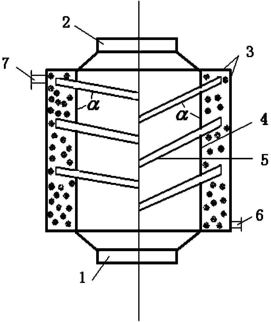
[0016] see figure 1 , The steel inner shell and outer shell are welded into a water jacket structure cylinder, and a set of heat pipes are welded on the inner wall of the water jacket. The flue gas inlet flange and the flue gas outlet flange are welded at both ends of the cylinder so as to be connected in series between the boiler and the root of the chimney to penetrate the flue gas passage. The water outlet pipe and the water inlet pipe are welded up and down on the water sleeve body so as to be connected in series to the return water pipe of the heating system. When the hot flue gas flows through the middle of the water jacket, it absorbs heat through the heat pipe to reduce the temperature of the flue gas and then discharges it. After the heat pipe absorbs heat, it transfers to the water jacket to raise the water temperature, and the water after the temperature r...


PUM


Abstract

The invention discloses a flue gas waste heat recovery device for heat pipes. The device comprises a water sleeve body formed by an inner casing and an outer casing. The set of heat pipes are welded on the inner wall of the water sleeve body, a flue gas inlet flange and a flue gas outlet flange are welded at the upper end and the lower end of the water sleeve body respectively, a water outgoing pipe is welded at the top of the water sleeve body, and a water ingoing pipe is welded at the bottom of the water sleeve body. The flue gas inlet flange is connected with a boiler flue gas outlet, and the flue gas outlet flange is connected with the root of a chimney. The water ingoing pipe and the water outgoing pipe are in series connection in a heating system water return pipe, and the water outgoing pipe is connected with a boiler water return port. The flue gas waste heat recovery device for heat pipes has the advantages of reducing fuel consumption of an atmospheric pressure boiler, reducing exhaust gas temperature, and improving operation heat efficiency of the boiler.

Description

Technical field: [0001] The invention belongs to the field of energy saving, and relates to a small atmospheric boiler flue gas waste heat recovery technology, in particular to a heat pipe flue gas waste heat recovery device. Background technique: [0002] Due to the simple manufacturing process, small steel consumption, low cost, and safe and convenient use of small boilers, especially atmospheric boilers, their production and use scale have developed extremely rapidly in recent years, and have been widely used in various enterprises, institutions, organizations, and hotels in urban and rural areas of our country. Heating, bathing, drinking water, chemical industry and other fields in restaurants, urban residential areas. However, its technology develops slowly, and its design, manufacture, installation and use are at a relatively low level, and there are common problems such as large fuel consumption, high exhaust gas temperature, and low thermal efficiency of operation. ...

Claims


Application Information

Patent Timeline
IPC IPC(8): F24H1/26F24H9/00
Inventor 柴俊彦郭启明唐娴
Owner 陕西火王能源科技有限责任公司
Why Eureka
Try Eureka