
Position calibration method and device for distributed optical fiber sensing system

A technology of distributed optical fiber and sensing system, which is applied in the direction of measuring devices, instruments, thermometers, etc., can solve the problems of accurate correspondence and achieve the effect of convenient installation

Active Publication Date: 2013-12-04
CHNA ENERGY INVESTMENT CORP LTD +2
View PDF8 Cites 15 Cited by
  • Summary
  • Abstract
  • Description
  • Claims
  • Application Information

AI Technical Summary

Problems solved by technology

After the sensing optical fiber is arranged, the computer needs the parameters measured by a certain section of optical fiber to correspond to the spatial position, that is, to know where the parameter event measured by the optical fiber occurs, and this cannot be determined based on the length of the optical fiber laid from the central computer room to the field. make accurate correspondence

Method used


Image

  • Position calibration method and device for distributed optical fiber sensing system
  • Position calibration method and device for distributed optical fiber sensing system
  • Position calibration method and device for distributed optical fiber sensing system

Examples


Embodiment Construction

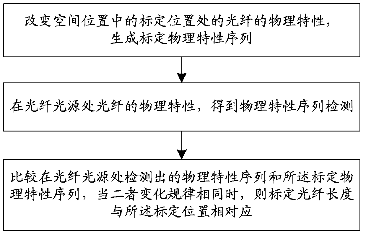
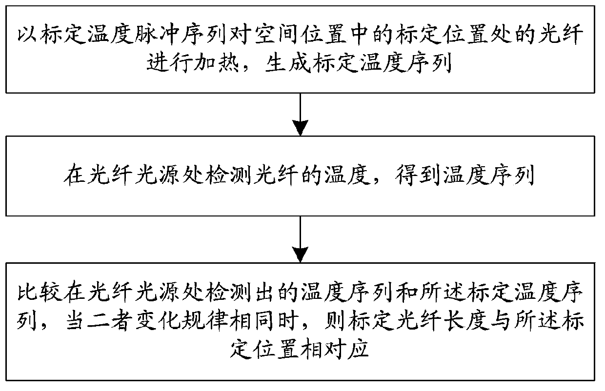
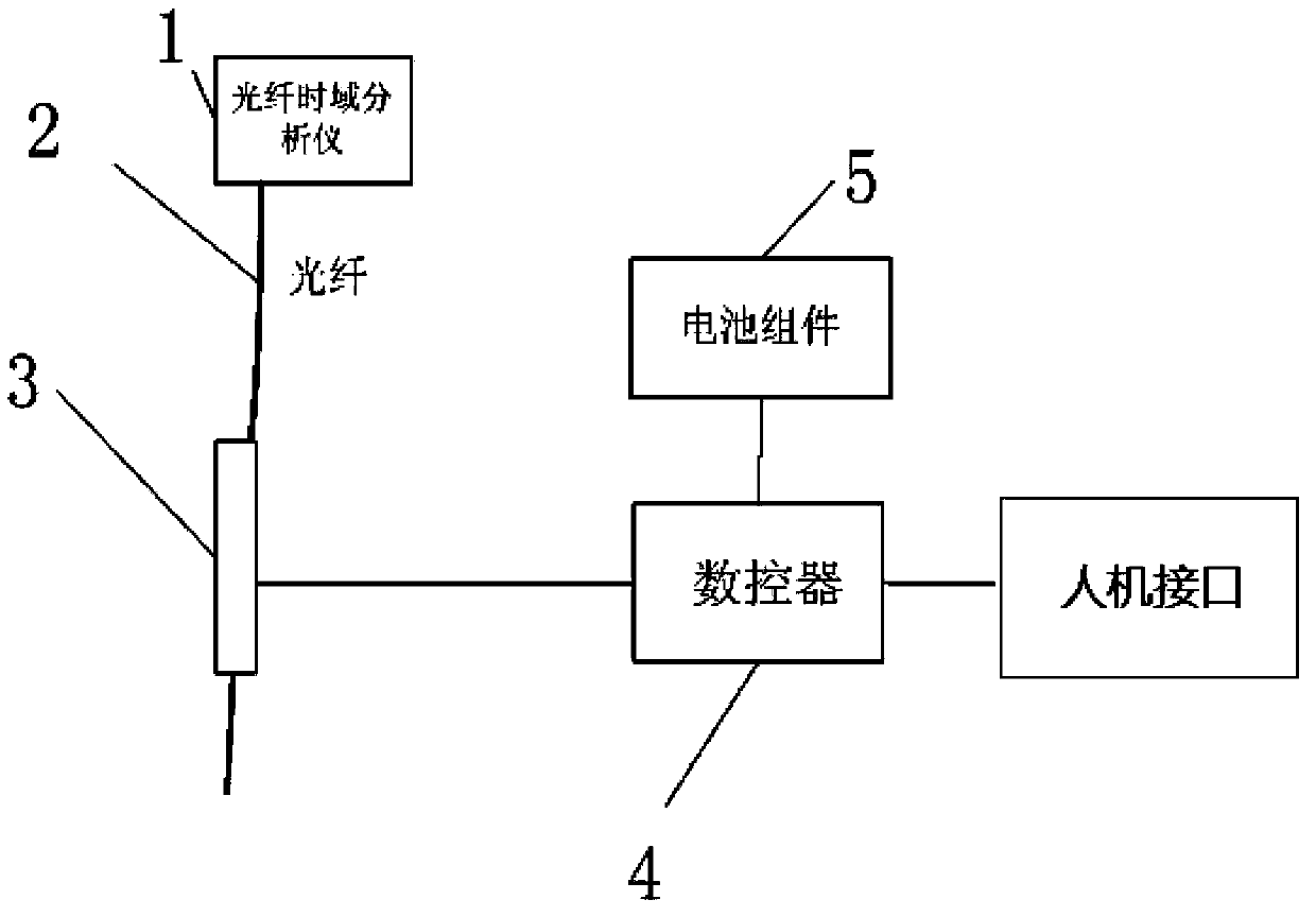
[0020] figure 1 A flow chart of the position calibration method for the distributed optical fiber sensing system of the present invention is shown. It includes step a): changing the physical properties of the optical fiber at the calibration position in the spatial position, and generating a calibration physical property sequence. Step b): Detecting the physical characteristics of the optical fiber at the optical fiber light source to obtain a sequence of physical characteristics. Step c): comparing the physical property sequence detected at the optical fiber light source with the calibrated physical property sequence, and when the change rules of the two are the same, the calibrated optical fiber length corresponds to the calibrated position. Alternatively, changing the physical properties of the fiber can be regularly changing.

[0021] We know that when the physical characteristics of the optical fiber are changed, the optical characteristics of the optical fiber will cha...


PUM


Abstract

The invention provides a position calibration method for a distributed optical fiber sensing system. The position calibration method comprises the steps of (a) changing physical characteristics of an optical fiber at the calibrating position in a spatial position to generate a calibrating physical characteristic sequence; (b) detecting the physical characteristics of the optical fiber at the position of an optical fiber light source to obtain a physical characteristic sequence; (c) comparing the physical characteristic sequence detected at the position of the optical fiber light source with the calibrating physical characteristic sequence, wherein the calibrating optical fiber length corresponds to the calibrating position when change rules of the physical characteristic sequence and the calibrating physical characteristic sequence are identical. The invention further provides a corresponding position calibration device. The corresponding relation of the optical fiber length and the spatial position is established by performing position calibration to a plurality of different positions of the whole optical fiber by means of the position calibration method and the corresponding position calibration device.

Description

technical field [0001] The invention relates to the field of optical fiber sensing and testing, and more particularly relates to a position calibration method and device for a distributed optical fiber sensing system. Background technique [0002] A typical distributed optical fiber sensing system is used for temperature detection. The working principle is: temperature changes have an impact on the optical properties of the optical fiber (light scattering inside the optical fiber has temperature characteristics), and the sensing fiber is known by detecting changes in the optical properties of the optical fiber. The temperature of a certain section of optical fiber. The distributed optical fiber temperature sensing system sends high-power narrow-band optical pulses into the optical fiber, and detects the change of the returned scattered light intensity over time, so that the length of the optical fiber can be detected as a continuous function of distance over the entire conti...

Claims


Application Information

Patent Timeline
Patent Type & Authority Applications(China)
IPC IPC(8): G01D18/00G01K15/00G01L25/00
Inventor 杨吉平常鸿姚平林刚张学珠王恒晓叶常华王瑞林付沛霖
Owner CHNA ENERGY INVESTMENT CORP LTD
Learn More