Optical fiber temp/moisture sensor and manufacturing method and metering installation thereof

A technology of humidity sensor and optical fiber temperature, which is applied in the field of sensors, can solve the problems affecting the performance stability of humidity sensors, insufficient light intensity, and large binding loss, etc., which is beneficial to industrial applications, improves accuracy and sensitivity, and reduces the inter-individual difference effect

Inactive Publication Date: 2008-01-23
李亚滨
View PDF2 Cites 19 Cited by
  • Summary
  • Abstract
  • Description
  • Claims
  • Application Information

AI Technical Summary

Problems solved by technology

This requirement makes it difficult to adjust the refractive index in manufacturing, thus limiting the range of material choices
[0010] Secondly, generally speaking, the compatibility between the polymer material of the plastic optical fiber core and the cladding layer is poor, especially when using mixed materials, phase separation will often occur in the solution state, and it is easy to form an inhomogeneous Induction cladding layer, and there are problems such as the induction cladding layer is easy to peel off from the fiber core
Therefore, the individual difference of the humidity sensor is large, and the service life is short
[0011] In addition, when the plastic optical fiber core is used, since the core is also hygroscopic, it affects the performance stability of the humidity sensor, and because the plastic core is too affected by temperature, in the range of low humidity (less than 50%), Changes in output light intensity caused by large temperature changes will overwhelm changes in light intensity caused by changes in humidity
[0012] Again, the currently disclosed technology can only be dried at room temperature to form a film, without high-temperature aging treatment on the induction coating layer, so there is instability in structure and chemical properties, low precision, poor durability, and it is difficult to be practical.
[0013] Finally, due to the higher refractive index of the cladding layer than the core, the loss of light is large
If this kind of sensor is used to make a humidity measuring device, especially when long-distance transportation is required, there will not only be problems such as insufficient light intensity caused by the large light loss mentioned above, but also because the end area of ​​the plastic optical fiber constituting the sensor is several times that of a glass optical fiber. Therefore, the combination loss between the plastic core sensor and the glass optical fiber for transmission is too large to be practical at all.

Method used


Image

  • Optical fiber temp/moisture sensor and manufacturing method and metering installation thereof
  • Optical fiber temp/moisture sensor and manufacturing method and metering installation thereof
  • Optical fiber temp/moisture sensor and manufacturing method and metering installation thereof

Examples


Embodiment 1

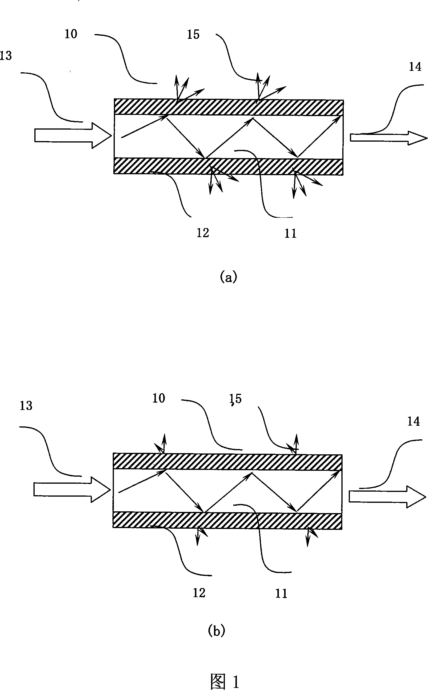
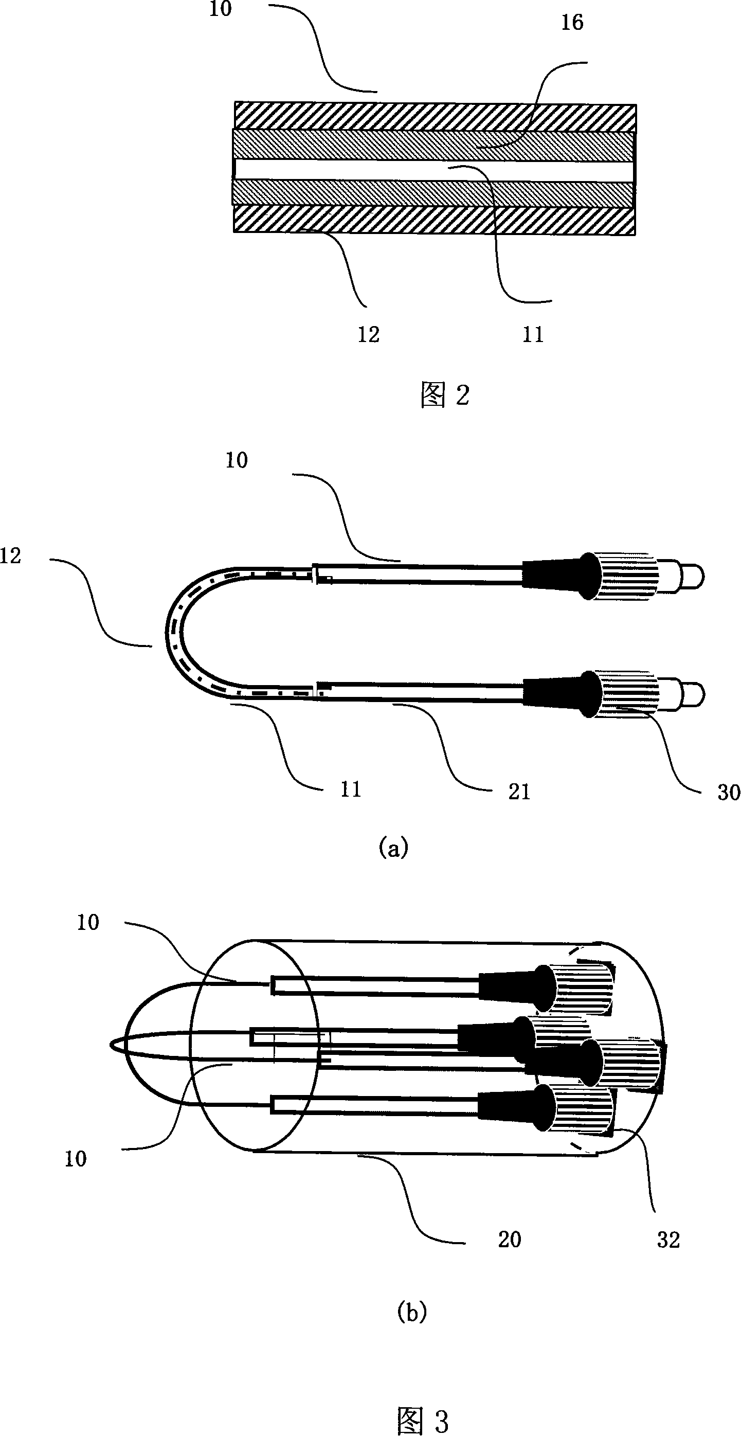
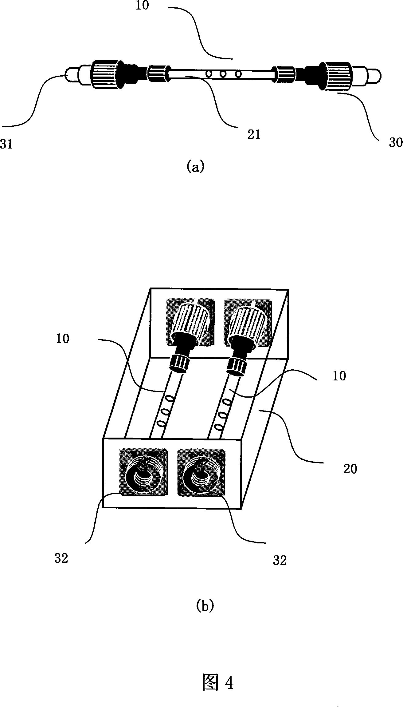
[0127] Cut a glass optical fiber with a core diameter of 200 μm (n=1.46, the diameter including the high polymer reflective layer is 230 μm) into a length of 30 cm, start from a position 2 cm away from one end, and dip the optical fiber in chloroform for 5 minutes , Peel off the high polymer reflective layer about 5cm. Then, heat the solution of polyvinylidene fluoride (PVDF, Tm=175°C, n=1.42) dissolved in cyclohexanone to 100°C and let it cool to 45°C. on the fiber core 11, and kept at room temperature for 10 hours. Afterwards, it is moved into a drying oven, and after heat treatment at 180° C. for 30 minutes in vacuum, a layer of transparent induction cladding layer 12 is formed on the surface of the glass fiber core 11 . Then use an adhesive to bond the two ends of the optical fiber to the ceramic ferrule 31, assemble the FC plug 30, and fully grind the end face of the optical fiber to make a temperature sensor.

[0128] The structure of the sensor testing system is (see ...

Embodiment 2

[0133] Dissolve 10 parts of PVDF and 1 part of polymethylphenylsilane (PMPS, Mw=30000, Tg=230°C, Tm=280°C, n=1.68) in cyclohexanone to prepare a 5% mixed solution, according to The procedure of Example 1 was applied to the same glass core used in Example 1. It was heat-treated at 220° C. for 30 minutes in vacuum. In this mixing ratio, PMPS is reduced to 1.55 under the specified heat treatment conditions, and the refractive index of the sensing cladding layer is 1.43, and an optical fiber temperature sensor is made.

[0134] According to the method of Example 1, after FC plugs are assembled at its two ends, it is placed in a constant temperature and humidity tank 50. Under the conditions of Example 1, the temperature response characteristics of the sensor are evaluated. It can be found that compared with Example 1, It has better temperature response characteristics.

[0135] The O-Si-O bond is formed between the PMPS of the sensor and the glass fiber core, which is integrated...

Embodiment 3

[0137] A PMMA optical fiber with a diameter of 250 μm was cut to a length of 10 cm, dipped in DMSO, and the reflective layer was stripped off. Dissolve 11 parts of PVDF and 2 parts of polymethylphenylsilane (PMPS, Tg=230°C, n=1.68) in cyclohexanone to prepare a 5% mixed solution, and coat it on PMMA according to the method of Example 1 on the fiber core. After vacuum-drying it at 80° C. for 12 minutes, an optical fiber temperature sensor is produced.

[0138] The FC plug 30 is connected to the two ends of the optical fiber temperature sensor with a ceramic ferrule 31, and the end faces are fully ground. This sensor is fixed in the protective box 20 (referring to Fig. 4 (b)), and in the constant temperature and humidity tank 50, the temperature response characteristic of the sensor is evaluated according to the conditions of Example 1, and the result shows that it has the same characteristics as the sensor of Example 1. Equivalent response characteristics.

[0139] In additi...


PUM

PropertyMeasurementUnit
diameteraaaaaaaaaa
diameteraaaaaaaaaa
thicknessaaaaaaaaaa

Abstract

The invention relates to an optic-fiber temperature/humidity sensor and the manufacturing method and application for the sensor. The optic-fiber temperature/humidity sensor is characterized in that, the sensor comprises an optic-fiber core with a refractivity of 0 and a sensing cladding layer with a refractivity of nc, and the sensing cladding layer contains at least one polymer or low-molecular material whose refractivity will change with temperature/humidity; the optic fiber is a glass or plastic optic fiber, the core diameter is 5 micrometer-3mm; the thickness of the sensing cladding layer is 0.1-30 micrometer, length not more than 20 cm. The sensor uses the optic-fiber core in the invention; and after the sensing cladding layer is heated to be completely molten in the solvent, the melt is cooled to 20-60 centigrade, then the solvent is evenly coated on the outer surface of the glass or plastic optic-fiber core; after airing, heat treatment or cross-link treatment, the sensor is obtained.

Description

technical field [0001] The invention relates to sensor technology, specifically an optical fiber temperature sensor, an optical fiber humidity sensor, a manufacturing method thereof, and a temperature and humidity measuring device using them. The international patent classification number is proposed to be Int.C1.G01K11 / 32 (2006.01). Background technique [0002] Optical fibers have the characteristics of thin diameter, light weight, and insulators, which are beneficial to use in areas with strong electromagnetic noise and high voltage without interference, especially glass optical fibers have the advantages of being able to be used in high temperature and flammable gas environments. The research of this fiber optic sensor is the focus. [0003] A special optical fiber can be obtained by doping inorganic materials such as Er whose refractive index can be changed in glass. The fiber is irradiated with laser light to change the refractive index of Er in the fiber core, so tha...

Claims


Application Information

Patent Timeline
Patent Type & Authority Applications(China)
IPC IPC(8): G01K11/32G01N21/41G02B6/02
Inventor 梁传信
Owner 李亚滨
Why Eureka
Try Eureka