Underwater super-cavity producing device free of production of interferential cavity flows

A generation device, non-interference technology, applied in the direction of measuring device, fluid dynamics test, machine/structural component test, etc., can solve the problems affecting the observation and research of supercavitation, unfavorable natural cavitation research, complex supercavitation flow field and other problems, to achieve the effect of simple structure, easy loading and unloading, and low cost

Inactive Publication Date: 2013-12-04
ZHEJIANG SCI-TECH UNIV
View PDF6 Cites 17 Cited by
  • Summary
  • Abstract
  • Description
  • Claims
  • Application Information

AI Technical Summary

Problems solved by technology

[0004] During the experiment, the gas at the front of the projectile in the launch tube enters the water earlier than the projectile under the high-speed drive of the projectile, which creates a disturbance section that interferes with the flow field and affects the initial development state of the supercavitation

Method used


Image

  • Underwater super-cavity producing device free of production of interferential cavity flows
  • Underwater super-cavity producing device free of production of interferential cavity flows
  • Underwater super-cavity producing device free of production of interferential cavity flows

Examples


Embodiment Construction

[0020] The present invention will be further described below in conjunction with the accompanying drawings and embodiments.

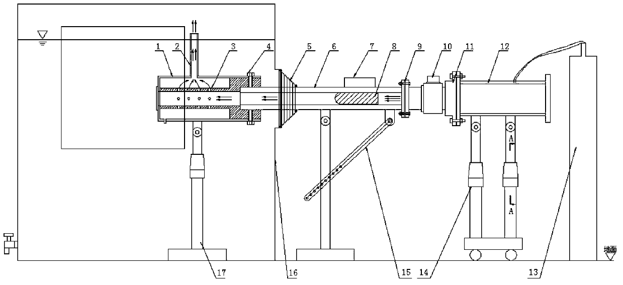
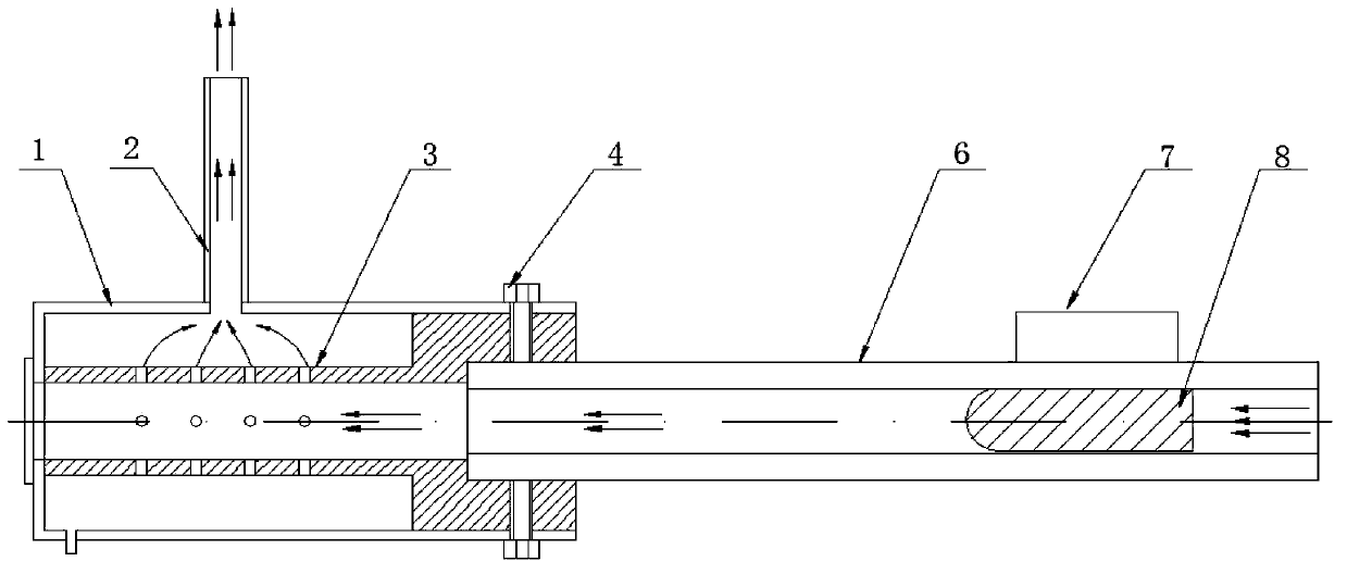
[0021] as attached figure 1 , figure 2 As shown, the present invention includes a muffler cylinder 1, an exhaust pipe 2, an exhaust cylinder 3, a set screw 4, a sealing hose 5, a launch tube 6, a positioning magnet 7, an elastic body 8, a pipe valve connector 9, and a solenoid valve 10, cylinder valve connector 11, high-pressure cylinder 12, high-pressure air source 13, cylinder support 14, launch tube support 15, water tank 16, muffler tube support 17; The plexiglass can observe the water level in the water tank 16 and the process of cavitation generation and development after the launch of the projectile 8; there is a water level adjustment device on the left side of the water tank 16, and the water level in the water tank 16 can be changed by controlling the water level adjustment device; There is a flange hole on the wall, and a sealing hose 5 is...


PUM


Abstract

The invention discloses an underwater super-cavity producing device free of production of interferential cavity flows. An observation window is arranged on a water tank, a sealing hose is installed outside a flange hole on the side wall, one end of an emission tube is inserted into the water tank through the sealing hose and then installed at one end of an exhaust tube inside a silencing tube, an air outlet hole at the top of the silencing tube is connected with an exhaust tube, a drain hole is formed in the lower portion of the front end, a missile body ejection hole is formed in the front portion, and a support which can be used for adjusting the height of the silencing tube is fixed inside the water tank; the other end of the emission tube is connected with a high-pressure air source through a tube valve connector, a solenoid valve, a cylinder valve connector and a high-pressure air cylinder, a positioning magnet is arranged on an outer cylindrical surface of the other end of the emission tube, a missile body is installed inside a hole at the other end of the emission tube, which corresponds to the positioning magnet, and a support which can be used for adjusting the angle of the emission tube and a support which can be used for adjusting the height of the high-pressure air cylinder are fixed on the ground. According to the underwater super-cavity producing device, the mechanism study on cavity development processes free of production of disturbance sections under the conditions of different water depths and different emission angles is conducted through adjustment of different diving angles of the missile body, adjustment of different water levels of the water tank and cooperation with a flow field visualization instrument.

Description

technical field [0001] The invention relates to an experimental device for fluid dynamic behavior and characteristics, in particular to an underwater supercavitation generating device for generation of non-interfering cavitation flow. Background technique [0002] When the vehicle is running horizontally and at high speed in the water, the liquid around the vehicle will vaporize, thus creating cavitation bubbles covering the surface of the vehicle. When the vehicle is surrounded by the entire gas, we call this gas region a natural superfluous region. Cavitation, at this time, the vehicle runs in the cavity, and the resistance of the vehicle is greatly reduced. With the development of society and the advancement of science and technology, the research results related to supercavitation have been widely and importantly applied in the field of marine transportation industry and natural science, especially in military defense technology. [0003] Natural supercavitation and ven...

Claims


Application Information

Patent Timeline
IPC IPC(8): G01M10/00
Inventor 陈波胡青青施红辉胡俊辉王昀
Owner ZHEJIANG SCI-TECH UNIV
Why Eureka
Try Eureka