Non-rotary optical rotation solution gauge and method for measuring specific rotation of optical rotation solution through gauge

A non-rotating, measuring instrument technology, applied in the direction of polarization influence characteristics, etc., to achieve the effect of real-time observation

Active Publication Date: 2013-12-04
锐光凯奇(镇江)光电科技有限公司
View PDF5 Cites 8 Cited by
  • Summary
  • Abstract
  • Description
  • Claims
  • Application Information

AI Technical Summary

Problems solved by technology

[0007] In order to solve the problem that the existing instruments for measuring optically active substances need to continuously rotate the polarizer to determine the rotation angle of the vibration surface of the optically active soluti

Method used


Image

  • Non-rotary optical rotation solution gauge and method for measuring specific rotation of optical rotation solution through gauge
  • Non-rotary optical rotation solution gauge and method for measuring specific rotation of optical rotation solution through gauge
  • Non-rotary optical rotation solution gauge and method for measuring specific rotation of optical rotation solution through gauge

Examples


Example Embodiment

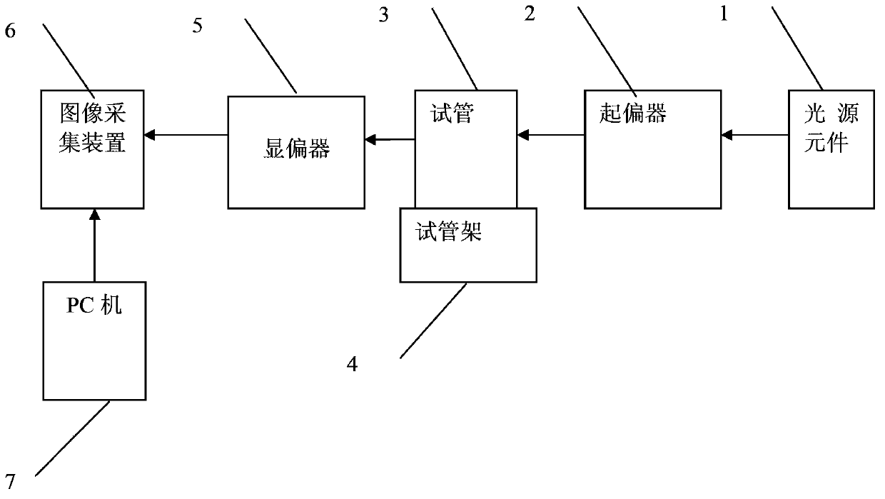
[0023] Specific implementation mode 1. Combination figure 1 Describe this embodiment, the non-rotating polarimetric solution measuring instrument of this embodiment, the polarimeter includes a light source element 1, a polarizer 2, a test tube 3, a test tube rack 4, a polarizer 5, an image acquisition device 6 and a PC 7;

[0024] The light beam emitted by the light source element 1 is incident on the polarizer 2, and the linearly polarized light after being polarized by the polarizer 2 is incident on the test tube 3 containing the optically active solution, and the linearly polarized light after passing through the test tube 3 containing the optically active solution is incident on the The polarizer 4, the polarized light developed by the polarizer 4 is incident on the photosensitive surface of the image acquisition device 6, and the image acquisition device 6 sends the collected image information to the PC 7, and the test tube 3 is installed on the test tube rack 4 Above, t...

Example Embodiment

[0026] Embodiment 2. This embodiment is a further description of the non-rotating polarimetric solution measuring instrument described in Embodiment 1. The light source element 1 is realized by a laser or an LED light source. Use a laser or LED light source as the incident light source, irradiate on the polarizer, pass through the polarizer, and obtain the polarized direction of the incident light on the PC.

Example Embodiment

[0027] Embodiment 3. This embodiment is a further description of the non-rotating polarimetric solution measuring instrument described in Embodiment 1 or Embodiment 2. The image acquisition device 6 is realized by a CCD camera.

[0028] The CCD camera is used to display the image of the linearly polarized light after 4 in real time, and the outgoing direction of the linearly polarized light can be accurately obtained through the software processing on the PC.


PUM


Abstract

The invention provides a non-rotary optical rotation solution gauge and a method for measuring the specific rotation of optical rotation solution through the gauge, relates to a method for measuring the optical rotation solution, and solves the problem that the conventional instrument for measuring the optical rotation material requires that an analyzer is continuously rotated when the specific rotation of the solution is measured to confirm the rotating angle of a vibrating surface of the optical rotation solution. The method comprises the following steps: utilizing light beams emitted by a light source element to be incident to a polarizer; enabling linearly polarized light polarized by the polarizer to be incident to a test tube filled with optical rotation solution; enabling the linearly polarized light passing by the test tube filled with optical rotation solution to be incident to a polarization displaying device; enabling the linearly polarized light displayed by the polarization displaying device to be incident to a light sensing surface of an image collecting device; sending image information collected by the image collecting device to a PC; calculating the difference value of the polarization direction of light beams in light beam information obtained after the solution to be measured is measured and the polarization direction of light beams in light beam information obtained through a solution not measured through the PC, so as to obtain the optical rotation theta of the solution to be measured; finally obtaining the specific rotation of the solution to be measured. According to the invention, the gauge and the method can be used for measuring the optical rotation solution.

Description

technical field [0001] The invention relates to a method for measuring an optically active solution. Background technique [0002] After the linearly polarized light passes through the solution of certain substances, the vibration plane of the polarized light will rotate at a certain angle with the direction of light propagation as the axis. This phenomenon is called optical rotation. The angle of rotation is called the optical rotation of the substance. A polarimeter is usually used to measure the optical rotation of a substance. [0003] Optically active substances can be divided into right-handed and left-handed. When viewed from the direction of light, if the vibrating surface rotates clockwise, it is called a right-handed substance; if the vibrating surface rotates counterclockwise, it is called a left-handed substance. [0004] In the existing measurement of optically active substances, on the optical bench, the laser beam emitted by the semiconductor laser, the pol...

Claims


Application Information

Patent Timeline
IPC IPC(8): G01N21/21
Inventor 齐晓岩吕尊仁单旭晨马宇曹远高来勖黄妍刘书钢
Owner 锐光凯奇(镇江)光电科技有限公司
Why Eureka
Try Eureka