Rotary electromagnetic heating device of conical rotor

A technology of electromagnetic heating device and conical rotor, which is applied in induction heating device, induction heating, water heater and other directions, can solve the problems of low external energy, single temperature adjustment method, and inability to make full use of it, so as to achieve a wide range of power systems, The effect of extending the temperature adjustable range

Inactive Publication Date: 2013-12-04
HARBIN INST OF TECH
View PDF3 Cites 3 Cited by
  • Summary
  • Abstract
  • Description
  • Claims
  • Application Information

AI Technical Summary

Problems solved by technology

[0003] The present invention proposes a conical rotor rotating electromagnetic heating device in order to solve the singleness of the temperature adjustment method of the traditional electromagnetic heating device and the problem that the external energy cannot be fully utilized when the external energy is low.

Method used


Image

  • Rotary electromagnetic heating device of conical rotor
  • Rotary electromagnetic heating device of conical rotor
  • Rotary electromagnetic heating device of conical rotor

Examples


specific Embodiment approach 1

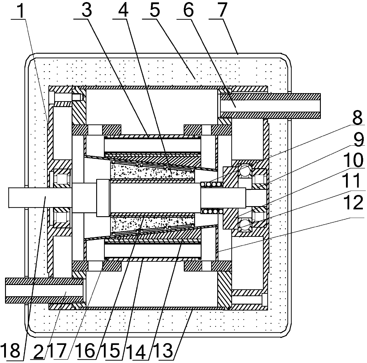
[0019] Specific implementation mode one: see figure 1 and figure 2 Description of this embodiment, a conical rotor rotating electromagnetic heating device, which includes an end cover 1, an outlet 2, a stator part, a rotor part, an insulation layer 5, an inlet 6, an outer cover 7, a pressure spring 8, a cylindrical roller bearing 9, a slidable Pressure ring 10, thrust ball bearing 11, sealing cover 12 and shaft 18,

[0020] The stator part is composed of a stator core 3, a number of conductive strips 14, a number of conduits 15, a short-circuit ring 17 and an outer jacket 13,

[0021] The inner axial section of the stator core 3 is isosceles trapezoidal, and the outer part is cylindrical. There are a number of through holes in the axial direction inside the stator core. The through holes are evenly distributed along the circumferential direction with the axis 18 as the center. A conductive strip 14 and a conduit 15 are placed in the hole, the short-circuit ring 17 is arrang...

specific Embodiment approach 2

[0029] Specific implementation mode two: see figure 2 Describe this implementation mode, this implementation mode is to further limit the specific implementation mode 1,

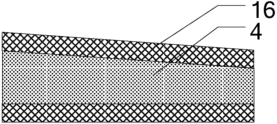
[0030] The rotor component includes a rotor core 16 and a permanent magnet 4 with a pole pair number p, wherein p is 4, 6, 8 or 10,

[0031] The rotor component is a built-in tangential structure, the rotor core 16 is a circular platform structure, the center of the rotor core 16 is provided with a through hole, and the permanent magnet 4 is tangentially embedded in the interior of the rotor core 16, and the cross section of each permanent magnet 4 along the axial direction is trapezoidal, and the distance between the outer surface of each permanent magnet 4 and the surface of the stator is uniform and equal.

specific Embodiment approach 3

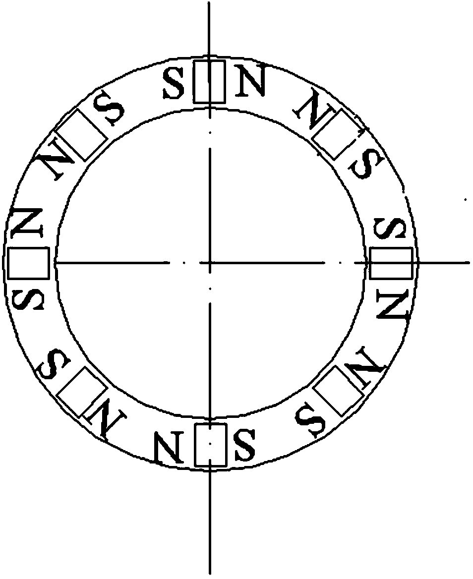
[0032] Specific implementation mode three: see image 3 Describe this embodiment. This embodiment is a further limitation of the second specific embodiment. The permanent magnet 4 is magnetized in a tangential direction along the rotation direction of the rotor, and the magnetization direction of two adjacent permanent magnets 4 along the rotation direction on the contrary.

[0033] In this embodiment, the permanent magnet 4 is magnetized along the tangential direction, and the two adjacent permanent magnet blocks are arranged tangentially facing the same polarity, that is, the magnetic guide yoke between the two adjacent permanent magnet blocks has a polarity of S or N , two adjacent magnetic yokes are of opposite polarity, forming p pairs of poles.


PUM


Abstract

The invention discloses a rotary electromagnetic heating device of a conical rotor, and belongs to the technical field of motor application. The rotary electromagnetic heating device solves the problem that in a traditional electromagnetic heating device, the temperature adjusting way is single and when external energy is low, the energy cannot be fully utilized. The axial cross section of the inner portion of a stator iron core of the rotary electromagnetic heating device of the conical rotor is in the shape of an isosceles trapezoid, the outer portion of the stator iron core of the rotary electromagnetic heating device of the conical rotor is columnar, the outer surface of a conical rotor iron core can be machined to have certain taper, and permanent magnets can also be used for maintaining the taper. The permanent magnets can be permanent magnets which are of a surface-mounted-type structure and can also be built-in-type permanent magnets. The magnetizing direction of the permanent magnets can be tangential and can also be radial. A pressure spring and a slidable pressing ring form an air gap adjusting mechanism, a shaft is connected with an external power device, and axial movement of rotors is realized through the conical rotor and the air gap adjusting mechanism, so that an air gap magnetic field is adjustable, and therefore the traditional electromagnetic heating device is improved and the temperature adjustable range of the traditional electromagnetic heating device is expanded. The rotary electromagnetic heating device of the conical rotor can be widely applied to the fields like heating and bathing.

Description

technical field [0001] The invention belongs to the technical field of motor application. Background technique [0002] For traditional rotating electromagnetic heating devices, when the structure is determined, the output heat power can only be changed by changing the input of external power. When wind energy is used as the power input system, it cannot be fully utilized at low speeds. Contents of the invention [0003] The present invention proposes a conical rotor rotating electromagnetic heating device in order to solve the problem of the singleness of the temperature regulation method of the traditional electromagnetic heating device and the problem that the external energy cannot be fully utilized when the external energy is low. [0004] Conical rotor rotating electromagnetic heating device, which includes end cover, outlet, stator part, rotor part, insulation layer, inlet, outer cover, pressure spring, cylindrical roller bearing, slidable pressure ring, thrust bal...

Claims


Application Information

Patent Timeline
Patent Type & Authority Applications(China)
IPC IPC(8): H05B6/10F24H1/10
Inventor 程树康柴凤陈磊裴宇龙于艳君李楠
Owner HARBIN INST OF TECH
Why Eureka
Try Eureka