Rotary electromagnetic heating device of conical rotor
A technology of electromagnetic heating device and conical rotor, which is applied in induction heating device, induction heating, water heater and other directions, can solve the problems of low external energy, single temperature adjustment method, and inability to make full use of it, and achieve extended temperature adjustment. Wide range of effects, powertrain
- Summary
- Abstract
- Description
- Claims
- Application Information
AI Technical Summary
Problems solved by technology
Method used
Image
Examples
specific Embodiment approach 1
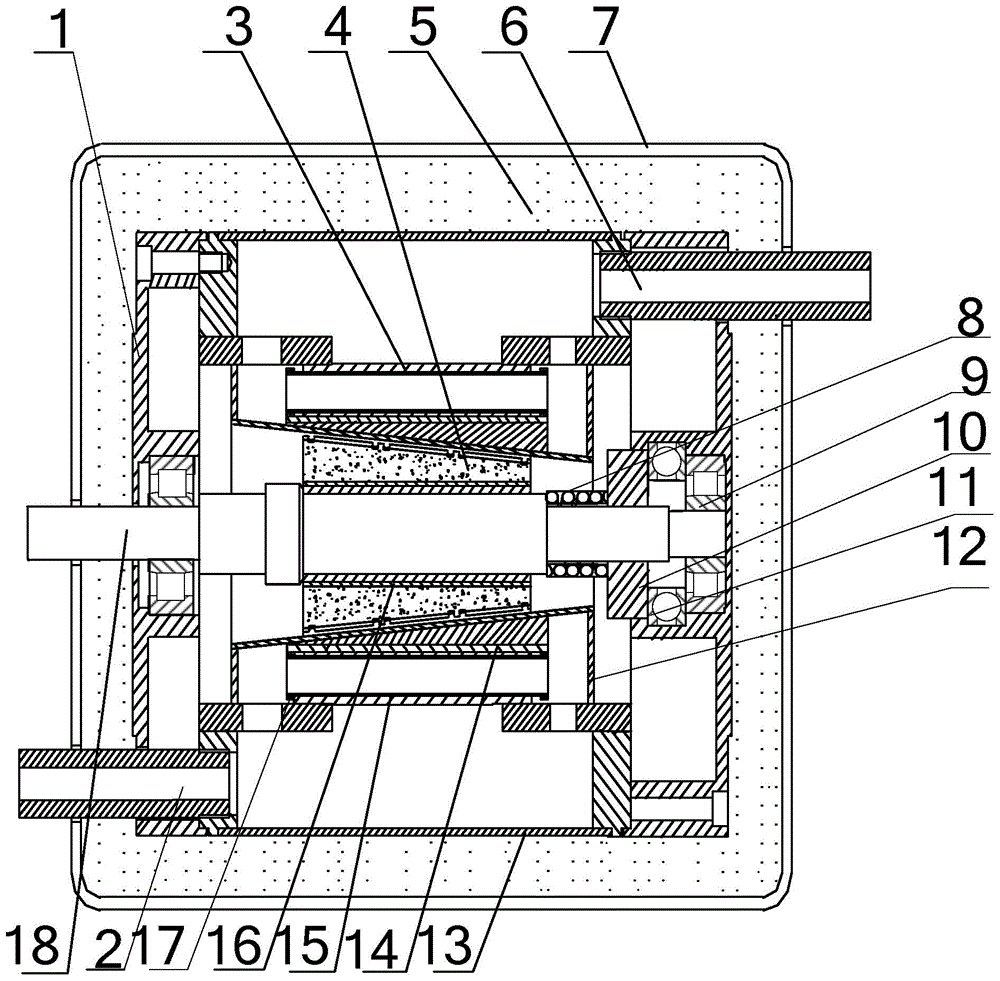
[0019] Specific implementation mode one: see figure 1 and figure 2 Description of this embodiment, a conical rotor rotating electromagnetic heating device, which includes an end cover 1, an outlet 2, a stator part, a rotor part, an insulation layer 5, an inlet 6, an outer cover 7, a pressure spring 8, a cylindrical roller bearing 9, a slidable Pressure ring 10, thrust ball bearing 11, sealing cover 12 and shaft 18,
[0020] The stator part is composed of a stator core 3, a number of conductive strips 14, a number of conduits 15, a short-circuit ring 17 and an outer jacket 13,
[0021] The inner axial section of the stator core 3 is isosceles trapezoidal, and the outer part is cylindrical. There are a number of through holes in the axial direction inside the stator core. The through holes are evenly distributed along the circumferential direction with the axis 18 as the center. A conductive strip 14 and a conduit 15 are placed in the hole, the short-circuit ring 17 is arrang...
specific Embodiment approach 2
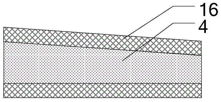
[0029] Specific implementation mode two: see figure 2 Describe this implementation mode, this implementation mode is to further limit the specific implementation mode 1,
[0030] The rotor component includes a rotor core 16 and a permanent magnet 4 with a pole pair number p, wherein p is 4, 6, 8 or 10,
[0031] The rotor component is a built-in tangential structure, the rotor core 16 is a circular platform structure, the center of the rotor core 16 is provided with a through hole, and the permanent magnet 4 is tangentially embedded in the interior of the rotor core 16, and the cross section of each permanent magnet 4 along the axial direction is trapezoidal, and the distance between the outer surface of each permanent magnet 4 and the surface of the stator is uniform and equal.
specific Embodiment approach 3
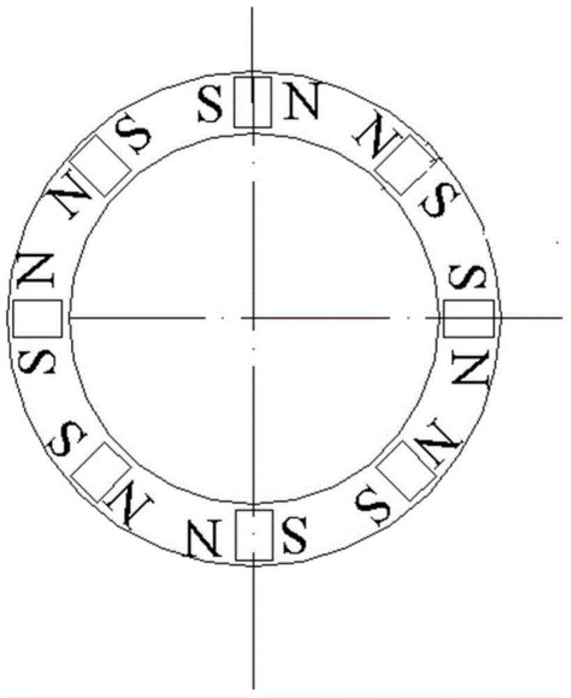
[0032] Specific implementation mode three: see image 3 Describe this embodiment. This embodiment is a further limitation of the second specific embodiment. The permanent magnet 4 is magnetized in a tangential direction along the rotation direction of the rotor, and the magnetization direction of two adjacent permanent magnets 4 along the rotation direction on the contrary.
[0033] In this embodiment, the permanent magnet 4 is magnetized along the tangential direction, and the two adjacent permanent magnet blocks are arranged tangentially facing the same polarity, that is, the magnetic guide yoke between the two adjacent permanent magnet blocks has a polarity of S or N , two adjacent magnetic yokes are of opposite polarity, forming p pairs of poles.
PUM
 Abstract
Description
Claims
Application Information
 - R&D
- Intellectual Property
- Life Sciences
- Materials
- Tech Scout
- Unparalleled Data Quality
- Higher Quality Content
- 60% Fewer Hallucinations
Browse by: Latest US Patents, China's latest patents, Technical Efficacy Thesaurus, Application Domain, Technology Topic, Popular Technical Reports.
© 2025 PatSnap. All rights reserved.Legal|Privacy policy|Modern Slavery Act Transparency Statement|Sitemap|About US| Contact US: help@patsnap.com


