Hydraulic machine

A technology for hydraulic presses and presses, applied in the field of hydraulic presses, can solve the problems of impeller and pump body collision and friction, stuck, parking, etc., and achieves the effect of improving inner hole accuracy, avoiding collision friction and stuck, and easy to use.

Inactive Publication Date: 2013-12-11
孟轲
View PDF5 Cites 2 Cited by
  • Summary
  • Abstract
  • Description
  • Claims
  • Application Information

AI Technical Summary

Problems solved by technology

[0003] After the plastic impeller of the automobile engine water pump is injection-molded by the injection molding machine, the inner hole of the plastic impeller of the automobile engine water pump is relatively rough, the precision is low, and the concentricity between the inner hole and the outer circle is unqualified. Collision and friction with the pump body, or even stuck phenomenon, resulting in accidental parking

Method used


Image

  • Hydraulic machine

Examples


Embodiment 1

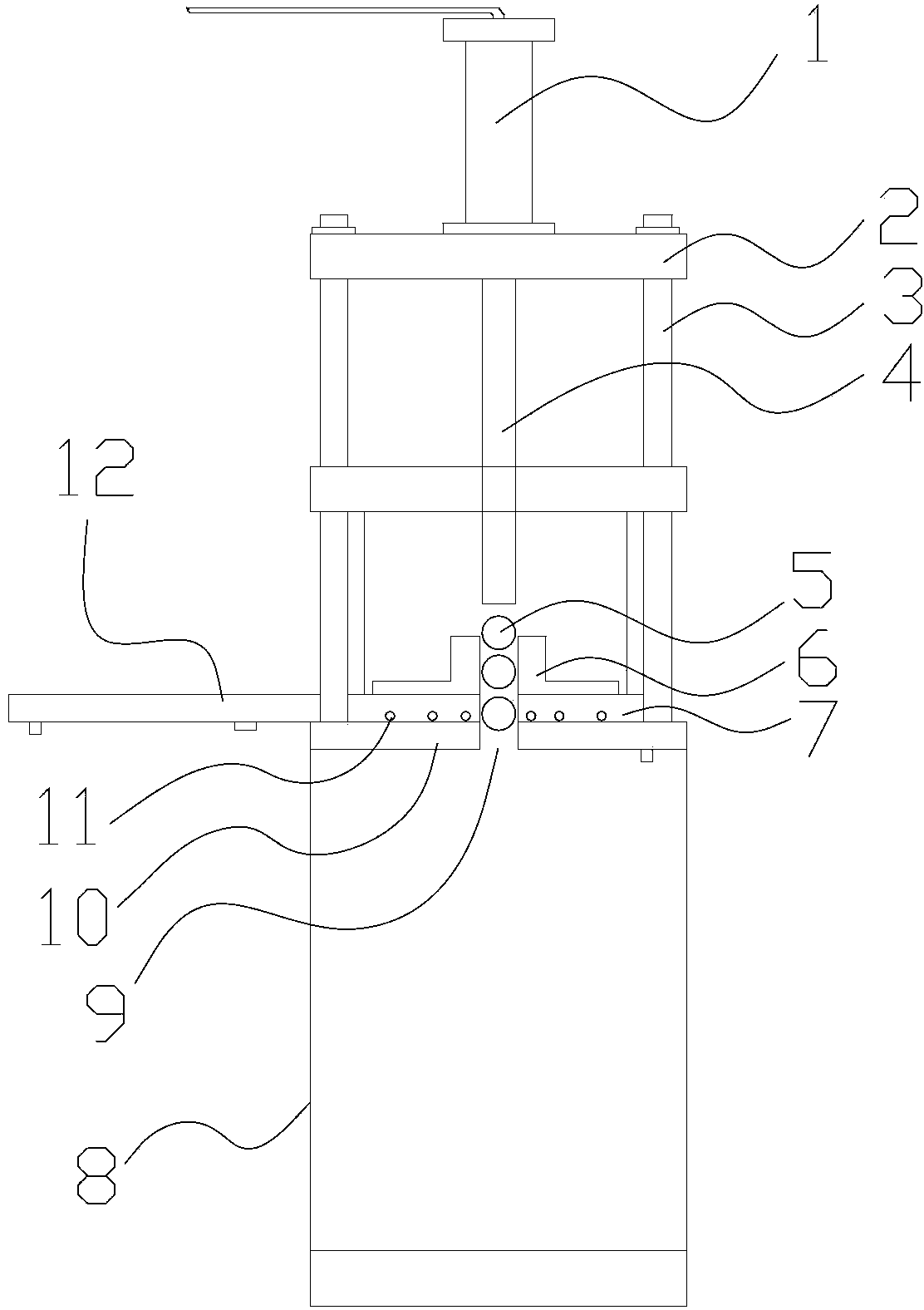
[0015] This embodiment relates to a hydraulic machine, such as figure 1 As shown, including: press 1, support 8, steel ball 5, base 7, lower support plate 10, the center of upper support plate 2, base 7 and support plate 10 is provided with through hole 9, and base 7 is provided with Fix the fixing bolt of the plastic impeller of the water pump of the automobile engine, the lower support plate 10 is arranged on the top of the support 8, the base 7 is arranged on the top of the lower support plate 10, and the centers of the base 7 and the lower support plate 10 are all provided with a through hole 9, and the upper The support plate 2 is fixed above the bracket 8 by the guide post 3, the guide post 3 is evenly distributed around, the base 7 and the lower support plate 10 are located between the upper support plate 2 and the bracket 8, and the top center of the upper support plate 2 A press 1 is provided, the output shaft of the press 1 is connected with a guide rod 4, and the gu...

Embodiment 2

[0017] This embodiment relates to a hydraulic machine, such as figure 1 As shown, including: press 1, support 8, steel ball 5, base 7, lower support plate 10, the center of upper support plate 2, base 7 and support plate 10 is provided with through hole 9, and base 7 is provided with Fix the fixing bolt of the plastic impeller of the water pump of the automobile engine, the lower support plate 10 is arranged on the top of the support 8, the base 7 is arranged on the top of the lower support plate 10, and the centers of the base 7 and the lower support plate 10 are all provided with a through hole 9, and the upper The support plate 2 is fixed above the bracket 8 by the guide post 3, the guide post 3 is evenly distributed around, the base 7 and the lower support plate 10 are located between the upper support plate 2 and the bracket 8, and the top center of the upper support plate 2 A press 1 is provided, the output shaft of the press 1 is connected with a guide rod 4, the guide ...

Embodiment 3

[0019] This embodiment relates to a hydraulic machine, such as figure 1 As shown, including: press 1, support 8, steel ball 5, base 7, lower support plate 10, the center of upper support plate 2, base 7 and support plate 10 is provided with through hole 9, and base 7 is provided with Fix the fixing bolt of the plastic impeller of the water pump of the automobile engine, the lower support plate 10 is arranged on the top of the support 8, the base 7 is arranged on the top of the lower support plate 10, and the centers of the base 7 and the lower support plate 10 are all provided with a through hole 9, and the upper The support plate 2 is fixed on the top of the support 8 by the guide post 3, the guide post 3 is evenly distributed around, the base 7 and the lower support plate 10 are located between the upper support plate 2 and the support 8, and the top center of the upper support plate 2 is provided with Press machine 1, the output shaft of press machine 1 is connected with gu...


PUM


Abstract

The invention provides a hydraulic machine. The hydraulic machine comprises a pressing machine, a support, steel balls, a base, a lower supporting plate and an upper supporting plate, wherein the base is provided with a fixed bolt for fixing a plastic impeller of a water pump of an automobile engine; the lower supporting plate and the base are sequentially arranged at the top end of the support, and the center of each of the base and the lower supporting plate is provided with a through hole; the upper supporting plate is fixed above the support through guide pillars, the center of the top end of the upper supporting plate is provided with the pressing machine, and an output shaft of the pressing machine is connected with a guiding rod; the diameter of each through hole is greater than or equal to that of each steel ball, the plastic impeller of the water pump of the automobile engine is firstly fixed on the base, and then the steel balls pass through an inner hole of the plastic impeller of the water pump of the automobile engine from top to bottom under the pressure action of the guiding rod, so that the polished finish on the inner hole of the plastic impeller of the water pump of the automobile engine is realized. The hydraulic machine provided by the invention has the advantages that the precision of the inner hole of the plastic impeller of the water pump of the injection moulding automobile engine is improved, and the use is convenient.

Description

technical field [0001] The invention relates to a plastic impeller processing device for an automobile engine water pump, in particular to a hydraulic machine. Background technique [0002] The water pump is an important part of the engine cooling system. Its function is to pump the coolant, so that the coolant flows quickly in the cooling water channel of the engine, so as to take away the heat generated when the engine is working and maintain the normal operating temperature of the engine. The water pump used in the automobile engine is a centrifugal water pump, which is composed of a housing, an impeller, a bearing, a pump shaft, a water seal, and a drive pulley. The impeller is the core component of the water pump. It is driven by the motor to rotate, so that a vacuum is generated in the middle of the impeller, and water will flow into the vacuum (on the surface, the impeller continuously sucks water in), and then the water is discharged through the high-speed rotating i...

Claims


Application Information

Patent Timeline
Patent Type & Authority Applications(China)
IPC IPC(8): B24C3/32B24C7/00
Inventor 孟轲
Owner 孟轲
Why Eureka
Try Eureka