Hoisting method and hoisting device for concrete prefabricated box beam

A hoisting device and hoisting method technology, applied in bridges, bridge construction, transportation and packaging, etc., can solve the problems of box girder hoisting holes and abdomen damage, difficulty in installing box girder in place, hidden dangers of rope hoisting, etc. Less damage, balanced hoisting, long service life

Active Publication Date: 2013-12-11
CHINA 19TH METALLURGICAL CORP
View PDF5 Cites 11 Cited by
  • Summary
  • Abstract
  • Description
  • Claims
  • Application Information

AI Technical Summary

Problems solved by technology

[0002] It is known that concrete prefabricated box girders have been widely used in bridge engineering, but due to the large volume of prefabricated box girders, large machines such as bridge erecting machines are usually used in the erection process, but steel wire ropes (or slings) are usually used when bridge erecting machines cannot be used ) through the hoisting hole to bind the box girder, and then hang the rope on the gantry crane or the crane hook to realize the handling and erection of the box girder. Due to the contact mode between the rope and the box girder, it is easy to make the box girder hoisting hole and belly etc., and it is easy to cause damage to the rope, which not only affects the quality of the box girder, but also brings safety hazards to the hoisting of the reused rope
When hoisting, both ends need to be hoisted at the same time, but due to the high flexibility of the rope, it is easy to cause sideways inclination of the box girder, which brings great difficulties to the installation of the box girder and requires constant adjustment

Method used


Image

  • Hoisting method and hoisting device for concrete prefabricated box beam
  • Hoisting method and hoisting device for concrete prefabricated box beam
  • Hoisting method and hoisting device for concrete prefabricated box beam

Examples


Embodiment

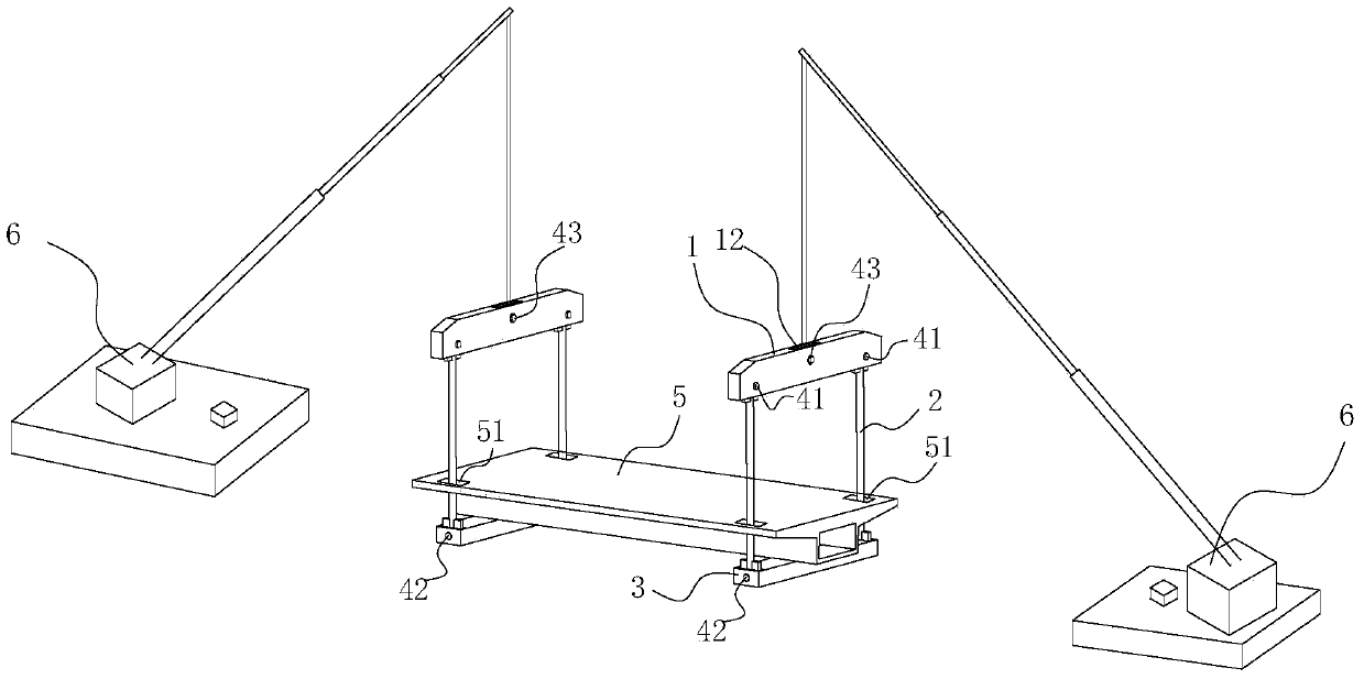
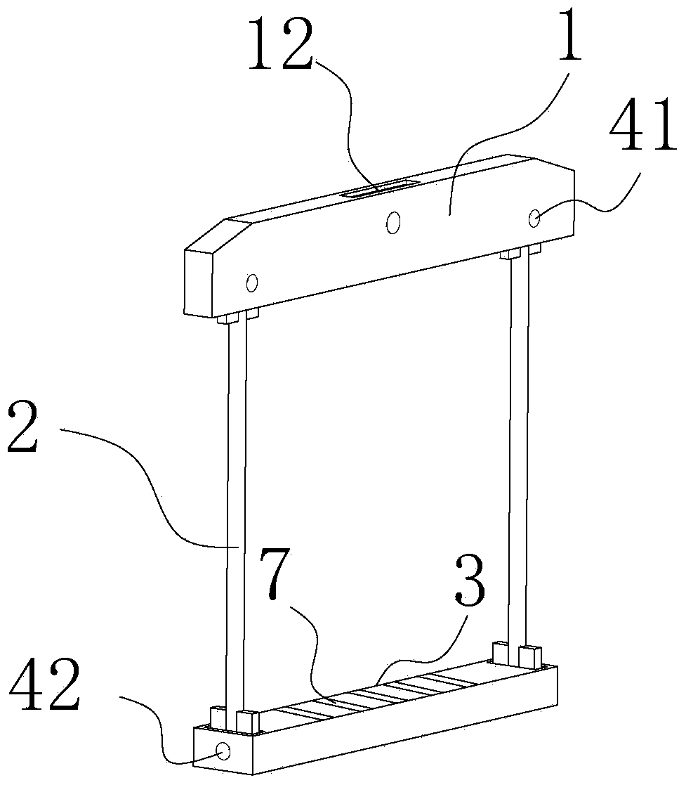
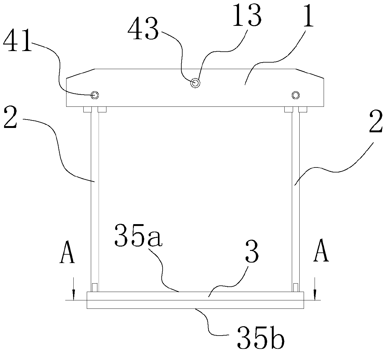
[0053] Such as Figure 2 to Figure 8 As shown, the concrete prefabricated box girder hoisting device includes a balance beam 1, a connecting rod 2, and a beam 3. Both ends of the balance beam 1 are connected to the connecting rod 2 through a first connection structure, and the two ends of the beam 3 are connected through a second connection. The structure is connected with the connecting rod 2 which is located between the balance beam 1 and the cross beam 3 . The balance beam 1 is provided with a hoisting structure. The first connection structure includes an upper pin shaft 41, pin holes 22 are provided at both ends of the connecting rod 2, and upper pin holes are provided on the balance beam 1; the second connection structure includes a lower pin shaft 42 , the beam 3 is provided with a lower pin hole 34; the upper pin 41 passes through the pin hole 22 at one end of the connecting rod 2 and matches with the upper pin hole on the balance beam 1, and the lower pin 42 passes th...


PUM


Abstract

The invention discloses a hoisting method and a hoisting device for a concrete prefabricated box beam. The hoisting method and the hoisting device can be used for reducing damage of the concrete prefabricated box beam in a hoisting process while ensuring that the prefabricated box beam is horizontal in the hoisting process. The concrete prefabricated box beam hoisting device comprises a balance beam, a connecting rod and a cross beam. The hoisting method comprises the following steps of: mounting hoisting devices at the two ends of the concrete prefabricated box beam; starting the hoisting equipment to hoist the balance beam; adjusting the position of the concrete prefabricated box beam to be horizontal; driving the concrete prefabricated box beam by the cross beam to rise above a bridge pier; positioning and mounting. The hoisting device has compact structure and good stability and can be used for reducing damage of the concrete prefabricated box beam in the hoisting process; the hoisting device can be repeatedly used and has long service life; the hoisting method is simple to operate, and can ensure that the concrete prefabricated box beam is always at a horizontal position in the hoisting process so as to facilitate the positioning and obtain higher safety of the hoisting process.

Description

technical field [0001] The invention relates to the field of hoisting of prefabricated concrete box girders, in particular to a hoisting method and a hoisting device of prefabricated concrete box girders. Background technique [0002] It is known that concrete prefabricated box girders have been widely used in bridge engineering. However, due to the large volume of prefabricated box girders, large machines such as bridge erecting machines are usually used in the erection process, but steel wire ropes (or slings) are usually used when bridge erecting machines cannot be used. ) through the hoisting hole to bind the box girder, and then hang the rope on the gantry crane or the hook of the crane to realize the handling and erection of the box girder. Due to the contact mode between the rope and the box girder, it is easy to make the box girder hoisting hole and belly etc. are damaged, and at the same time, the ropes are easily damaged, which not only affects the quality of the b...

Claims


Application Information

Patent Timeline
Patent Type & Authority Applications(China)
IPC IPC(8): E01D21/00B66C1/22
Inventor 蔡仲斌胡伟山冯超李昕蕊冯书斌代权胡孝菊
Owner CHINA 19TH METALLURGICAL CORP
Why Eureka
Try Eureka