Continuously variable valve lift mechanism

A variable valve lift technology, which is applied in mechanical equipment, engine components, machines/engines, etc., can solve the problems of large space occupation and complex structure of valve lift devices, and achieve small space occupation, simple structure, and mechanical components. little effect

Active Publication Date: 2013-12-11
CHONGQING CHANGAN AUTOMOBILE CO LTD
View PDF11 Cites 20 Cited by
  • Summary
  • Abstract
  • Description
  • Claims
  • Application Information

AI Technical Summary

Problems solved by technology

Therefore, the structure of the valve lift device is relatively complicated, and the space occupied after installation is large, and the cylinder head needs to be greatly modified.

Method used


Image

  • Continuously variable valve lift mechanism
  • Continuously variable valve lift mechanism
  • Continuously variable valve lift mechanism

Examples


Embodiment Construction

[0021] Below in conjunction with accompanying drawing and embodiment the present invention will be further elaborated:

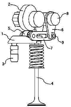
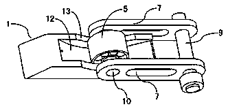
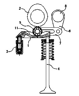
[0022] Such as figure 1 , figure 2 , image 3 , Figure 6 The continuously variable valve lift mechanism shown includes a rocker arm 1, a cam 2 arranged on a camshaft, a valve stem 4, a roller 5, an intermediate rod 7, a swing rod 6 arranged on a drive shaft 8, and a hydraulic lifter. Column 3, the axis of the drive shaft 8 is parallel to the axis of the camshaft, one end of the rocker arm 1 is supported and connected to the hydraulic tappet 3, the bottom surface of the other end of the rocker arm 1 is in contact with the valve stem 4, the Fork 6 is hinged with one end of intermediate rod 7 by connecting pin 9, and described roller 5 is installed on the other end of intermediate rod by bearing pin 10, and the distance between the axis of described cam 2 and the axis of drive shaft 8 is equal to the The distance between the axis of the pin shaft 10 and t...


PUM


Abstract

The invention relates to a continuously variable valve lift mechanism. The continuously variable valve lift mechanism comprises a rocker arm, a cam, a hydraulic tappet, a roller, a middle rod and a swing link, wherein one end of the rocker arm is supported against and connected with the hydraulic tappet, and the other end of the rocker arm is in contact with a valve rod; the swing link is hinged to one end of the middle rod through a connecting pin; the roller is arranged at the other end of the middle rod through a pin shaft; the top surface of the rocker arm is provided with a guide groove along the length direction; the roller is positioned in the guide groove and is in contact with the cam; the roller can move along the length direction of the guide groove under the driving of the middle rod. The continuously variable valve lift mechanism can realize continuously variable control of valve lift under different working conditions of an engine, has a simple structure and comprises a small number of members.

Description

technical field [0001] The invention relates to a valve control mechanism of an automobile engine, in particular to a continuously variable valve lift mechanism. Background technique [0002] For gasoline engines whose load is controlled by valve adjustment, because they often operate under partial load conditions, the residual exhaust gas coefficient is relatively high, so how to improve the combustion stability of the engine, reduce the low-load pumping loss, and organize the rapid combustion process, Improving combustion efficiency is extremely important. Therefore, when the engine is lightly loaded, it is hoped that the intake pressure difference will be increased through a small valve lift, thereby generating a higher air velocity, increasing turbulence, increasing flame propagation speed and combustion speed, and organizing a rapid combustion process. When the engine is at high speed and high load, a larger valve lift should be used to minimize the flow resistance, in...

Claims


Application Information

Patent Timeline
Patent Type & Authority Applications(China)
IPC IPC(8): F01L13/00
Inventor 张朝俊刘翠兰尚宇胡铁刚吴学松刘斌詹樟松
Owner CHONGQING CHANGAN AUTOMOBILE CO LTD
Why Eureka
Try Eureka