
A carbon fiber composite material metal diaphragm storage tank and its manufacturing method

A metal diaphragm and composite material technology, which is used in jet propulsion, mechanical equipment, rocket engine devices, etc., can solve the problem of no spherical pressure vessel implementation plan, limited mechanical environment adaptability, and failure to solve the problem of light weight products. To ensure the feasibility of the process, be conducive to deformation matching, and have strong adaptability to the mechanical environment

Active Publication Date: 2016-04-20
SHANGHAI INST OF SPACE PROPULSION
View PDF6 Cites 0 Cited by
  • Summary
  • Abstract
  • Description
  • Claims
  • Application Information

AI Technical Summary

Problems solved by technology

[0006] The invention patent of European Publication No. EP0941925A2 discloses a propellant tank, but this invention only provides the basic configuration of the metal diaphragm tank, and fails to solve the problem of lightweight design of the product
[0007] The invention patent of Chinese Patent Publication No. CN102275067 discloses a method for processing and preparing a hemispherical metal tank for spacecraft fuel. The method provides a method for manufacturing a titanium material metal diaphragm, which is easy to control the quality. As a preparation material, titanium thin plate is expensive, and there are certain difficulties in its popularization and application
This invention has the following limitations: firstly, this invention does not involve how to assemble the metal diaphragm management device; secondly, if the storage tank of this invention is filled with a large mass of propellant, its adaptability to the mechanical environment is limited. How to solve the technical approach of this problem, and the winding technology of this invention does not give the embodiment of spherical pressure vessel

Method used


Image

  • A carbon fiber composite material metal diaphragm storage tank and its manufacturing method
  • A carbon fiber composite material metal diaphragm storage tank and its manufacturing method

Examples


Embodiment Construction

[0052] The present invention will be described in detail below in conjunction with specific embodiments. The following examples will help those skilled in the art to further understand the present invention, but do not limit the present invention in any form. It should be noted that those skilled in the art can make several modifications and improvements without departing from the concept of the present invention. These all belong to the protection scope of the present invention.

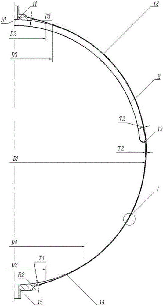
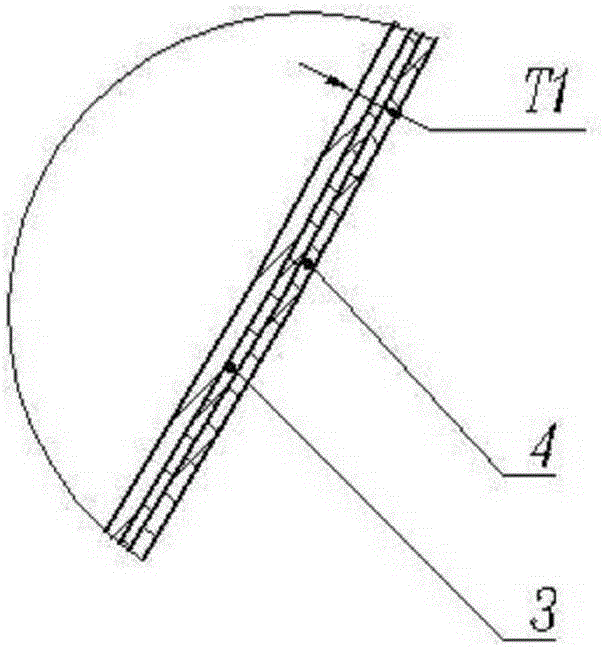
[0053] see figure 1 , a carbon fiber composite material metal diaphragm tank, including an inner liner 1 and a metal diaphragm 2, and also includes an insulating layer 3 and a carbon fiber composite material layer 4.

[0054] Liner 1 includes upper flange 11, upper hemisphere 12, connecting ring 13, lower hemisphere 14 and lower flange 15, upper hemisphere 12 and lower hemisphere 14 are connected by connecting ring 13, upper flange 11 is connected with upper hemisphere 12, lower The flange 15 is ...


PUM

PropertyMeasurementUnit
thicknessaaaaaaaaaa
diameteraaaaaaaaaa
thicknessaaaaaaaaaa

Abstract

The invention provides a metal diaphragm storage box made of carbon-fiber composite materials and a manufacturing method thereof. The metal diaphragm storage box comprises a liner 1 and a metal diaphragm 2 and also comprises an insulating layer 3 and a carbon-fiber composite material layer 4, wherein the liner 1 comprises an upper flange 11, an upper hemisphere 12, a connecting ring 13, a lower hemisphere 14 and a lower flange 15; the upper hemisphere 12 and the lower hemisphere 14 are connected by the connecting ring 13; the upper flange 11 is connected with the upper hemisphere 12; the lower flange 15 is connected with the lower hemisphere 14; the metal diaphragm 2 is butted with the connecting ring 13; the outer surface of the liner 1 is coated with the insulating layer 3; the outer surface of the insulating layer 3 is wound with the carbon-fiber composite material layer 4, and is connected with the carbon-fiber composite material layer 4 in a bonding manner. The metal diaphragm storage box provided by the invention has the advantages that the problems of large weight and low structure efficiency of the metal diaphragm storage box are solved, the light-weight design of the metal diaphragm storage box is realized, the cost is reduced and the performance of a product is improved.

Description

technical field [0001] The invention relates to a pressure vessel, in particular to a metal diaphragm storage tank made of carbon fiber composite material and a manufacturing method thereof. Background technique [0002] The propellant tank is a medium and low pressure pressure vessel with a liquid management device, designed for liquid attitude control power systems. The key issues of this kind of product are: on the one hand, it must have the ability to effectively manage liquids under space microgravity conditions (gas-liquid isolation); on the other hand, it must be able to withstand the mechanical environment assessment during launch (mechanical overload Wait). [0003] Commonly used propellant tank management devices include surface tension, metal diaphragms and non-metallic bladders. The main features of the metal diaphragm storage tank are: using the metal diaphragm to actively manage the propellant: on the one hand, under the action of the squeezed gas, the diaphr...

Claims


Application Information

Patent Timeline
Patent Type & Authority Patents(China)
IPC IPC(8): F02K9/60F02K9/44C08L63/00C08K7/06C08K3/04
Inventor 张璟邱卫东沈俊何才启施华韩洪武乔艳伟孔方圆魏彦祥曹伟陈剑李和军林森刘锋赵和明金广明
Owner SHANGHAI INST OF SPACE PROPULSION
Learn More