
Power transmission device for submersible pump and power transmission pipe thereof

A power transmission device and power transmission technology, applied in the field of hydraulic systems, can solve problems such as poor stability and reliability, inconvenient installation and maintenance, and achieve the effects of solving heating problems, simple maintenance and convenient installation.

Active Publication Date: 2016-01-20
WUHAN MARINE MACHINERY PLANT +1
View PDF6 Cites 0 Cited by
  • Summary
  • Abstract
  • Description
  • Claims
  • Application Information

AI Technical Summary

Problems solved by technology

[0006] In order to solve the problems of poor stability and reliability and inconvenient installation and maintenance of the long-axis power transmission device in the prior art, the embodiment of the present invention provides a power transmission device for a submersible pump and its power transmission tube

Method used


Image

  • Power transmission device for submersible pump and power transmission pipe thereof
  • Power transmission device for submersible pump and power transmission pipe thereof
  • Power transmission device for submersible pump and power transmission pipe thereof

Examples


Embodiment

[0028] In order to facilitate the understanding of the present invention, the structure of the submersible pump head will be briefly introduced below. The liquid pump is arranged in the housing of the submersible pump head.

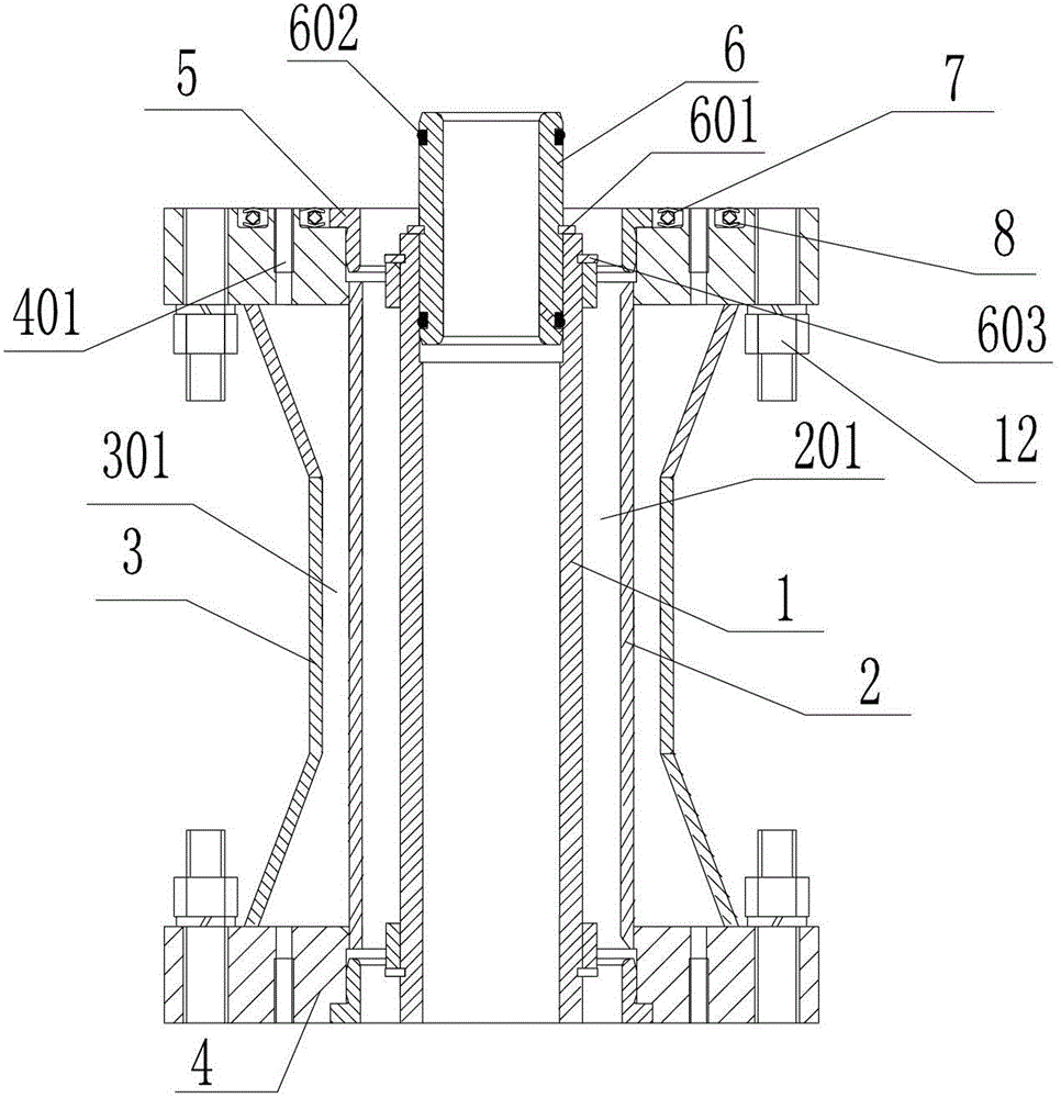
[0029] An embodiment of the present invention provides a power transmission device for a submersible pump, such as Figure 5 As shown, the power transmission device includes a hydraulic pump station, a submersible pump head 14 and a power transmission pipe 11, the hydraulic pump station includes a hydraulic pump 9, the submersible pump head 14 includes a motor for driving the submerged pump, and the power transmission pipe 11 One end of the pipe is communicated with the hydraulic pump 9, and the other end of the power transmission pipe 11 is communicated with the motor, wherein the hydraulic pump station is arranged on the deck.

[0030] Such as figure 1 As shown, the power transmission pipe 11 includes: a high-pressure oil inlet pipe 1 and a low-pressu...

Embodiment 2

[0045] An embodiment of the present invention provides a power transmission pipe for a submersible pump, such as Figure 5 As shown, the power transmission pipe 11 has a first end for communicating with the hydraulic pump 9 and a second end for communicating with the motor, and the first end and the second end are oppositely arranged along the axial direction of the power transmission pipe 14;

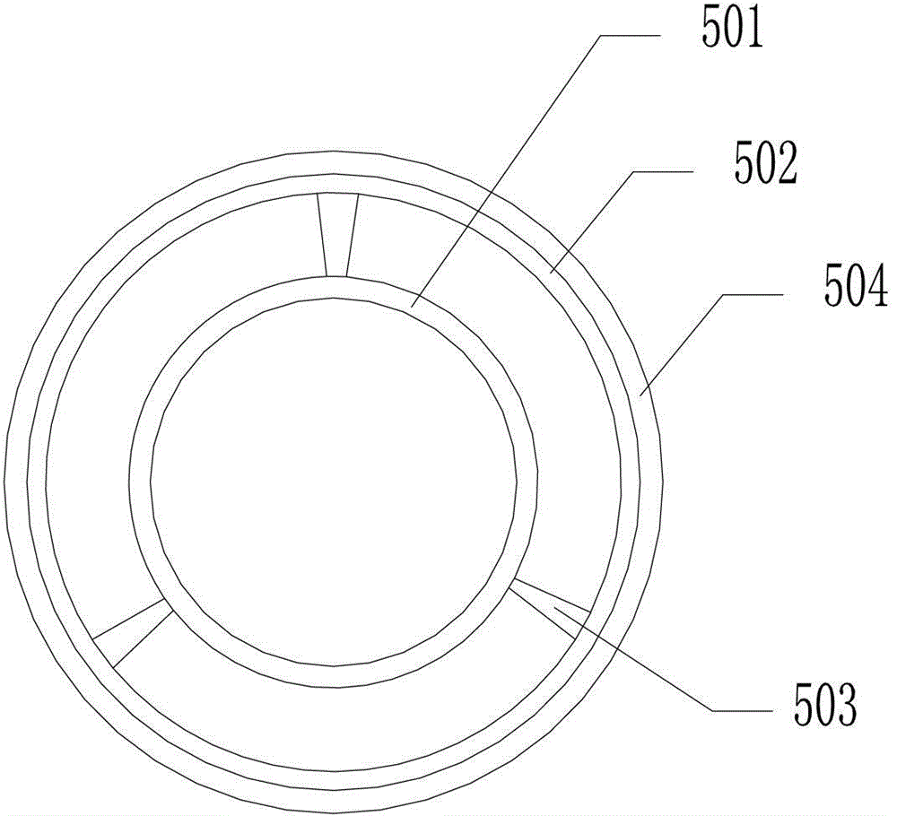
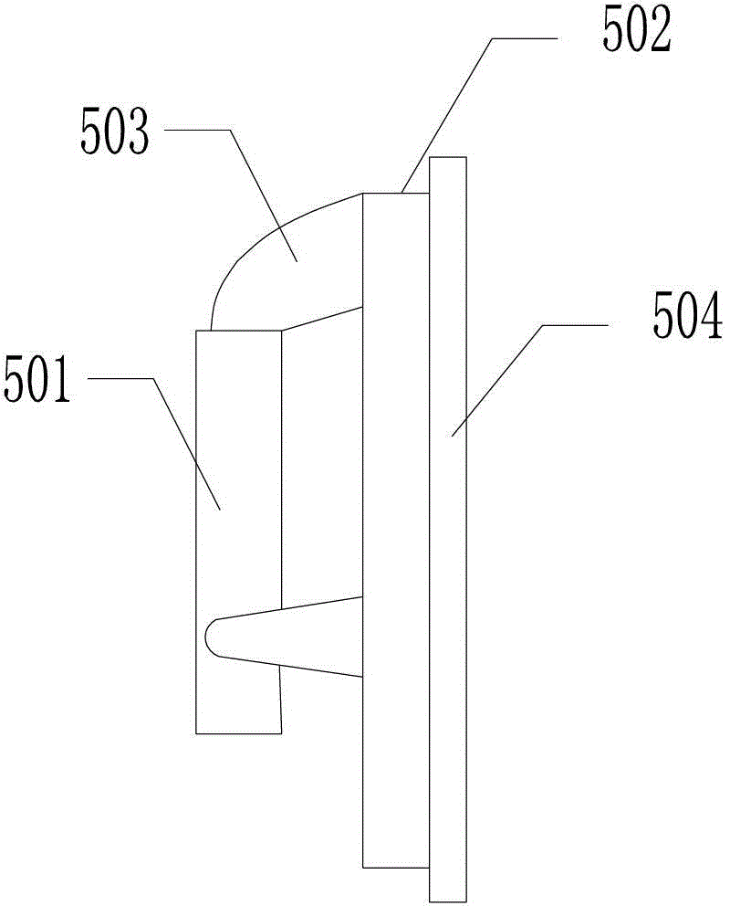
[0046] Such as figure 1 As shown, the power transmission pipe 11 includes: a high-pressure oil inlet pipe 1 and a low-pressure oil return pipe 2 arranged outside the high-pressure oil inlet pipe 1, the high-pressure oil inlet pipe 1 and the low-pressure oil return pipe 2 enclose a low-pressure oil return chamber 201, and the A support ring 5 is provided between the outer wall and the inner wall of the low-pressure oil return pipe 2, and the end of the power transmission pipe 11 communicating with the hydraulic pump is provided with a high-pressure connecting pipe 6, which is located in...


PUM


Abstract

The invention discloses a power transmission device for an immersed pump and a power transmission tube thereof, belonging to the field of a hydraulic system. The power transmission device for the immersed pump comprises a hydraulic pump station, an immersed pump head and a power transmission tube, wherein the hydraulic pump station comprises a hydraulic pump; the immersed pump head comprises an immersed pump and a motor for driving the immersed pump; one end of the power transmission tube is communicated with the hydraulic pump, and the other end of the power transmission tube is communicated with the motor; the power transmission tube comprises a high-pressure oil inlet tube and a low-pressure oil return tube which is arranged outside the high-pressure oil inlet tube; a low-pressure oil return cavity is enclosed by the high-pressure oil inlet tube and the low-pressure oil return tube; a supporting ring is arranged between the outer wall of the high-pressure oil inlet tube and the inner wall of the low-pressure oil return tube. The power transmission device for the immersed pump has high stability and good reliability and is convenient to mount and maintain. The power transmission tube has the characteristics of high rotation speed, long distance and high power.

Description

technical field [0001] The invention relates to the field of hydraulic systems, in particular to a power transmission pipe and a power transmission device for a submersible pump. Background technique [0002] The long-axis power transmission device for submersible pump is used to realize the power transmission between the hydraulic pump station on the deck of the oil tanker and the submersible pump of the liquid cargo bilge, and is the key equipment for the power transmission of the submersible pump of the oil tanker. [0003] The existing long-axis power transmission device includes a long-axis power transmission tube, a motor and a submersible pump head. The long-axis power transmission tube includes a sleeve and a rotating shaft located in the sleeve. One end of the rotating shaft is connected to the motor, and the rotating shaft The other end of the pump is connected to the submersible pump head, and the motor transmits power to the submersible pump head through the rota...

Claims


Application Information

Patent Timeline
Patent Type & Authority Patents(China)
IPC IPC(8): F04B17/00
Inventor 陈斌尤学刚赵雷刚朱江李东亮梁丰吕长龙刘旭
Owner WUHAN MARINE MACHINERY PLANT
Learn More