
Solar inner wall lens type compound parabolic concentrator with air interlayer

A compound paraboloid and air interlayer technology, which is applied in the field of solar energy utilization, can solve the problems of uneven light intensity distribution of concentrators and rising tracking costs, and achieve the effects of improving light intensity distribution, high geometric concentration ratio, and improving optical efficiency

Active Publication Date: 2014-12-10
UNIV OF SCI & TECH OF CHINA
View PDF4 Cites 0 Cited by
  • Summary
  • Abstract
  • Description
  • Claims
  • Application Information

AI Technical Summary

Problems solved by technology

[0003] In order to improve the concentrating ratio in the concentrator that restricts the acceptance angle, which leads to an increase in tracking costs or the situation that the concentrator can be fixedly installed but the concentrating ratio is small, and further optimize the problem of uneven light intensity distribution at the bottom of the concentrator after concentrating, The invention provides a solar inner wall lens type compound parabolic concentrator with an air interlayer

Method used


Image

  • Solar inner wall lens type compound parabolic concentrator with air interlayer
  • Solar inner wall lens type compound parabolic concentrator with air interlayer
  • Solar inner wall lens type compound parabolic concentrator with air interlayer

Examples


Embodiment 1

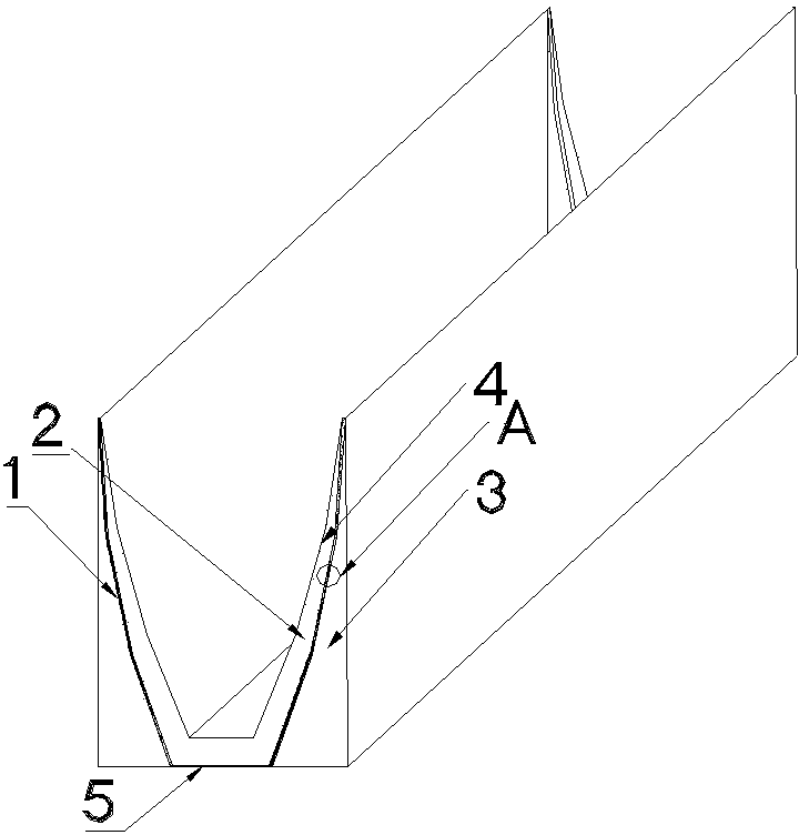
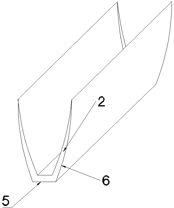
[0020] see figure 1 , the solar inner wall lens-type compound parabolic concentrator with an air interlayer includes a U-shaped compound parabolic concentrator as a whole, and the compound parabolic concentrator includes a frame 3 with a U-shaped cross section, and two compound parabolic reflectors 1 are respectively symmetrical Located on both sides of the frame 3; a lens 2 with a U cross section is installed between two compound parabolic reflectors 1. see figure 2 , taking the apex of the outer curved surface 6 as a fixed point, and rotating the outer curved surface 6 clockwise at an angle of 3 degrees around the fixed point to obtain the inner curved surface 4 . The thickness between the inner curved surface 4 and the outer curved surface 6 of the side walls on both sides of the lens 2 gradually increases from top to bottom, and the outer curved surfaces 6 of the side walls on both sides of the lens 2 match with the compound parabolic reflectors 1 on both sides respectiv...

Embodiment 2

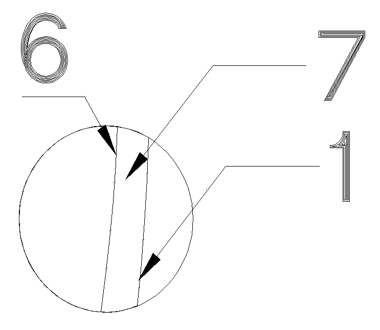
[0024] Taking the apex of the outer curved surface 6 as a fixed point, the outer curved surface 6 is rotated clockwise by 5 degrees around the fixed point to obtain the inner curved surface 4 . The air interlayer 7 has a thickness of 0.5 mm.

[0025] Others are with embodiment 1.


PUM


Abstract

The invention relates to a solar inner wall lens type compound parabolic concentrator with an air interlayer. The solar inner wall lens type compound parabolic concentrator comprises a compound parabolic concentrator, wherein the compound parabolic concentrator is integrally in a U shape, and the compound parabolic concentrator comprises a frame with a cross section formed in the U shape; two compound parabolic reflectors are symmetrically positioned at both sides inside the frame; a lens with the cross section formed in the U shape is arranged between the two compound parabolic reflectors; the thickness between the inner side curve surface and outer side curve surface of the side wall of the lens is gradually thickened from top to bottom; the outer side curve surfaces of both sides of the lens are respectively coincided with the compound parabolic reflectors positioned at both sides; gaps are arranged between the outer side curve surfaces and the corresponding compound parabolic reflector so that the air interlayer is formed. Compared with the common compound parabolic concentrator, the solar inner wall lens type compound parabolic concentrator disclosed by the invention enlarges the acceptance angle and can be used for absorbing the vertical incident sunlight scattered light within a larger range; the solar inner wall lens type compound parabolic concentrator disclosed by the invention can ensure higher concentration ratio, thereby achieving more obvious concentration effect.

Description

technical field [0001] The invention belongs to the technical field of solar energy utilization, and in particular relates to a deep-groove parabolic solar concentrator under composite concentrating light of a curved mirror surface and a lens. Background technique [0002] First of all, the existing compound parabolic concentrators are mainly trough-type mirror concentrators, that is, the reflecting surface is a compound paraboloid, and the whole is U-shaped. Through specular reflection, the direct light within the acceptance angle range can be collected to the bottom of the condenser according to the ideal concentration ratio, and the direct light outside the acceptance angle range will be reflected from the condenser slot through the mirror reflection. The geometric concentration ratio of the compound parabolic concentrator is numerically equal to the reciprocal of the sine of the maximum receiving half angle. Therefore, the larger the geometric concentration ratio, the s...

Claims


Application Information

Patent Timeline
Patent Type & Authority Patents(China)
IPC IPC(8): F24J2/12F24S23/71
CPCY02E10/42Y02E10/40
Inventor 裴刚李桂强苏跃红季杰
Owner UNIV OF SCI & TECH OF CHINA
Learn More