Optical fiber collimator

A technology of optical fiber collimator and optical fiber, which is applied in the coupling direction of optical waveguide, can solve the problems of low light absorption rate, huge data volume, and low optical coupling efficiency, and achieve simple assembly process, high optical coupling rate, and small volume small effect

Inactive Publication Date: 2014-07-16
深圳市天阳谷科技发展有限公司
View PDF13 Cites 1 Cited by
  • Summary
  • Abstract
  • Description
  • Claims
  • Application Information

AI Technical Summary

Problems solved by technology

[0003] However, single-mode fiber is a typical sudden-refractive-index fiber. The light of single-mode fiber diverges, which is not conducive to coupling to other devices, and the optical coupling efficiency is low; when single-mode fiber is used as a fiber for receiving light, the light absorption rate It is not high, and the optical coupling efficiency is also low; at present, optical fibers are widely used in various fields such as communication, and the amount of data transmitted by them is also very large; and in experiments such as silicon optics, it is often difficult to align optical fibers to planar waveguides

Method used


Image

  • Optical fiber collimator
  • Optical fiber collimator
  • Optical fiber collimator

Examples


Embodiment 1

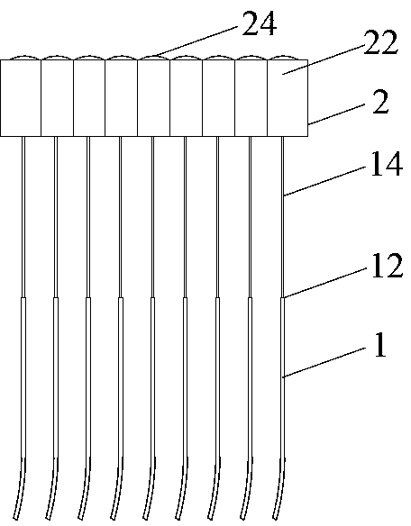
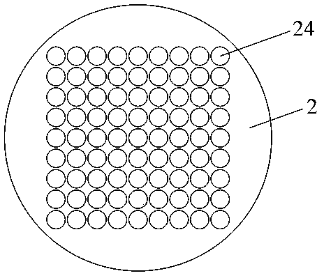
[0024] like figure 1 , figure 2 , Figure 5 As shown, the present invention proposes an optical fiber collimator, comprising 81 optical fibers 1 and 81 free-form surface self-focusing lenses 2, the optical fiber 1 is a quartz fiber, and the material of the free-form surface self-focusing lens 2 is optical molded glass , 81 free-form surface self-focusing lenses 2 are arranged in a 9×9 array and are integrated; the optical fiber 1 includes a coating layer 12 and a core 14, and one end of the core 14 is exposed on the coating Outside the layer 12; the free-form surface self-focusing lens 2 includes a cuboid part 22 and a free-form surface part 24, the free-form surface part 24 is a convex spherical surface, and the free-form surface part 24 is arranged on the center of the minimum surface of the cuboid part 22 position, the free-form surface part 24 is coated with a reflective film, the smallest surface of the cuboid part 22 is slightly larger than the free-form surface part ...

Embodiment 2

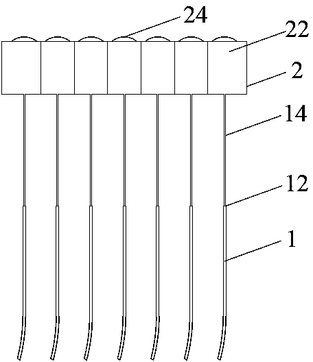
[0026] like image 3 , Figure 4 , Figure 5 As shown, the present invention proposes an optical fiber collimator, comprising 21 optical fibers 1 and 21 free-form surface self-focusing lenses 2, the optical fiber 1 is a glass optical fiber, and the material of the free-form surface self-focusing lens 2 is optical plastic. The 21 free-form surface self-focusing lenses 2 are arranged in a 7×3 array and are integrated; the optical fiber 1 includes a coating layer 12 and a core 14, and one end of the core 14 is exposed on the coating layer 12 outside; the free-form surface self-focusing lens 2 includes a cuboid part 22 and a free-form surface part 24, the free-form surface part 24 is an arc surface, and the free-form surface part 24 is arranged on the center of the minimum surface of the cuboid part 22 position, the free-form surface part 24 is coated with a reflective film, the smallest surface of the cuboid part 22 is slightly larger than the free-form surface part 24, and the...


PUM


Abstract

The invention discloses an optical fiber collimator. The optical fiber collimator comprises at least one optical fiber and free-form surface self-focusing lenses, wherein the number of the free-form surface self-focusing lenses corresponds to the number of the optical fibers. Each optical fiber comprises a coating layer and a fiber core, and one end of each fiber core is exposed out of the corresponding coating layer. Each free-form surface self-focusing lens comprises a cuboid part and a free-form surface part. the exposed portion of each fiber core is inserted into the corresponding cuboid part from the face opposite to the face of the corresponding free-form surface part and is tightly connected with the cuboid part into a whole, the total length of the exposed portions of the fiber cores is larger than the length of the portions, inserted into the cuboid parts, of the fiber cores, and optical axes of the free-form surface self-focusing lenses are concentric with the optical fibers. The optical fiber collimator is simple in structure, easy to assemble and low in insertion loss, the elements can be miniaturized, the optical fibers and the lenses are combined into a whole and can be singly used or used in an array mode, the optical fiber collimator has the advantages of being high in stability and reliability, small in size, light in weight and the like, and the size of the collimator can be miniaturized to the minimum.

Description

technical field [0001] The invention relates to the field of optical fiber communication network and optical fiber communication equipment, in particular to an optical fiber collimator, which collimates the light emitted by the optical fiber. Background technique [0002] Optical fiber is an abbreviation for optical fiber. It is a light transmission tool achieved by the principle of total reflection of light in fibers made of glass or plastic. It is widely used in various fields such as communication. According to the number of transmission modes in the fiber, the fiber can be divided into multi-mode fiber and single-mode fiber. Multimode fiber can adopt step refractive index distribution or graded refractive index distribution; single-mode fiber mostly adopts step refractive index distribution. Therefore, existing optical fibers can be classified into three types: multimode step-index fibers, multimode graded-index fibers and single-mode step-index fibers. [0003] Howeve...

Claims


Application Information

Patent Timeline
IPC IPC(8): G02B6/32
Inventor 黄燕平周小平张怀忠李立
Owner 深圳市天阳谷科技发展有限公司
Why Eureka
Try Eureka