Solar interior wall lens type composite parabolic concentrator applied to building south wall

A compound paraboloid and concentrator technology, applied in the field of solar energy utilization, can solve problems such as the limitation of light receiving angle, and achieve the effects of increasing the light receiving angle, improving uniformity, and improving the distribution of light intensity

Active Publication Date: 2017-03-22
UNIV OF SCI & TECH OF CHINA
View PDF4 Cites 1 Cited by
  • Summary
  • Abstract
  • Description
  • Claims
  • Application Information

AI Technical Summary

Problems solved by technology

[0003] In order to solve the limited problem of the light receiving angle when the traditional symmetrical concentrator is installed on the south wall of the building, under the condition of a certain concentration ratio, the concentrator is fixedly installed on the south wall of the building, so as to realize the guarantee of 8 hours a day throughout the year Solar Inner Wall Lens Type Compound Parabolic Concentrator for the South Wall of the Building at Sunlight Receiving Time

Method used


Image

  • Solar interior wall lens type composite parabolic concentrator applied to building south wall
  • Solar interior wall lens type composite parabolic concentrator applied to building south wall
  • Solar interior wall lens type composite parabolic concentrator applied to building south wall

Examples


Embodiment 1

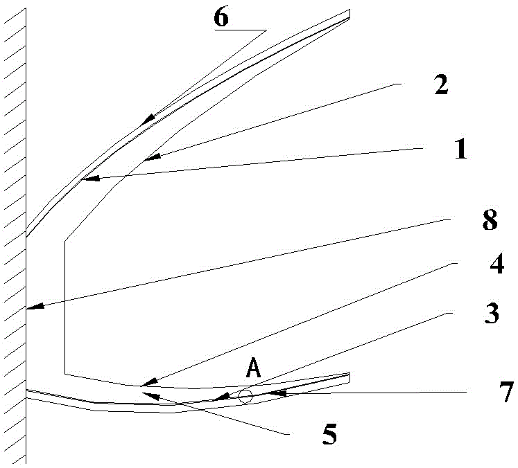
[0029] see figure 1 , the solar inner wall lens type compound parabolic concentrator used for the south wall of the building is an asymmetric U-shaped compound parabolic concentrator as a whole. It includes a lens 5 with an asymmetric U-shaped cross section, an upper compound parabolic reflector 6 , a lower compound parabolic reflector 7 and a frame, and the lens 5 is correspondingly installed between the upper compound parabolic reflector 6 and the lower compound parabolic reflector 7 . The light receiving angle of the concentrator is 20-80°.

[0030] The upper compound parabolic reflector 6 is designed with a maximum light receiving half angle of 42°, and the lower parabolic reflector 7 is designed with a maximum light receiving half angle of 0°.

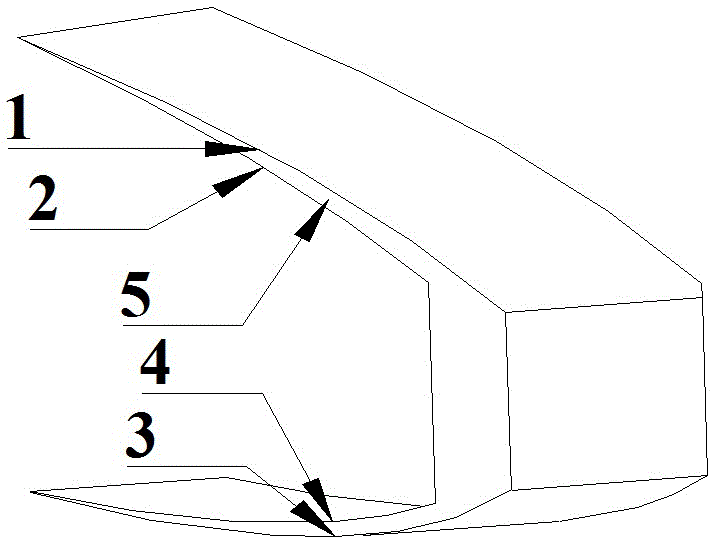
[0031] see image 3 , the outer curved surface and the inner curved surface of one side wall of the lens 5 are the upper outer compound paraboloid 1 and the upper inner curved surface 2 respectively, and the outer curved surface...

Embodiment 2

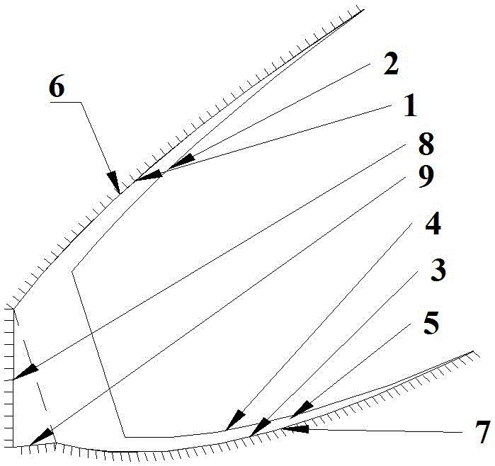
[0035] see figure 2 , in order to popularize and apply the concentrator of the present invention to low and middle latitude regions, the bottom surface of the concentrator is rotated counterclockwise around its upper top edge at an angle of 6° to form an included angle with the installation wall; Connected upright mirror surface 8 and connecting mirror surface 9, upright mirror surface 8 is connected with the inner edge of upper compound parabolic reflector 6 at the same time, connecting mirror surface 9 is connected with the inner end edge of lower compound paraboloid reflector 7 at the same time. The function of the connecting mirror 9 is to reflect light onto the upright mirror 8 .

[0036]Studies have shown that in this way, the range of the receiving angle of the concentrator can be effectively changed, so that it can also guarantee the annual receiving radiation time of 8 hours per day in low latitude areas. For example, in Beijing at 39°54’N116°23’E, the incident angl...

Embodiment 3

[0039] see figure 2 , the upright mirror 8 is disconnected from the main body of the light collector, and the geometric light collector of the light collector can be increased by reducing the length of the upright mirror 8 . The length of the upright mirror 8 is reduced to 5.6 mm, and the geometric light concentration ratio is increased to 2.75 without affecting the optical performance and acceptance angle of the light collector.

[0040] Other structures are with embodiment 1.


PUM

PropertyMeasurementUnit
Thicknessaaaaaaaaaa

Abstract

The invention relates to a solar interior wall lens type composite parabolic concentrator applied to a building south wall. The concentrator comprises a U-shaped lens, an upper composite parabolic reflector, a lower composite parabolic reflector and a frame. The whole concentrator is in an asymmetric U-shaped structure. The light receiving angle of the upper composite parabolic reflector is greater than the light receiving angle of the lower composite parabolic reflector. The range of the receiving angle of the condenser is between 0 degree and 80 degrees. When the concentrator provided by the invention is used, the bottom of the frame is fixedly arranged on the building south wall. Compared with a general concentrator combined with a building, the concentrator provided by the invention has the advantages that the building orientation is fully used; the concentrator is arranged in the external area of the building; the optimized structure provided by the invention is suitable for needs of different latitudes; the concentrator can maintain high optical efficiency in the receiving angle range; and except the case of large light incident angle due to structure and installation particularities, the light intensity distribution is uniform in other receiving angle ranges.

Description

technical field [0001] The invention relates to the field of solar energy utilization, in particular to a compound parabolic concentrator under compound light concentrating of an asymmetric curved mirror surface and a lens. Background technique [0002] The compound parabolic concentrator CPC (Welford and Winston, 1978) is a low-power concentration ratio non-imaging concentrator designed based on the principle of edge rays, which can collect the incident light within the acceptance angle range according to the ideal concentration ratio to the absorber, while incident light outside the range of acceptance angles will be reflected out of the condenser through the notch of the condenser. The geometric concentration ratio of the symmetrical compound parabolic concentrator is equal to the reciprocal of the sine of the maximum receiving half angle. Therefore, the larger the geometric concentration ratio, the smaller the corresponding maximum receiving half angle. When combined w...

Claims


Application Information

Patent Timeline
IPC IPC(8): G02B19/00F24J2/08F24J2/12F24S23/30F24S23/71
CPCF24S23/30F24S23/71G02B19/0028G02B19/0042Y02E10/40
Inventor 李桂强宣庆东裴刚季杰
Owner UNIV OF SCI & TECH OF CHINA
Why Eureka
Try Eureka