
Automatic detection device for commutator

An automatic detection device and detection device technology, applied in the direction of measuring devices, instruments, manipulators, etc., can solve problems such as difficulty in ensuring consistency in inspection, difficulty in ensuring quality, and unstable quality, so as to reduce the number of manual movements and avoid inconsistent inspections. The effect of ensuring dimensional consistency

Active Publication Date: 2013-12-11
三笠电器技研(苏州)有限公司 +2
View PDF9 Cites 21 Cited by
  • Summary
  • Abstract
  • Description
  • Claims
  • Application Information

AI Technical Summary

Problems solved by technology

[0003] When inspecting the inner hole of the product, the products are manually taken one by one and tested with the go-stop gauge. The go-gauge passes and the stop gauge stops. Repeated labor. The same is true for imports, time-consuming and difficult to guarantee quality
[0004] The detection of the angle of the hook is manually put into the jig and pressed in, which is dangerous and slow, and the manual handling of the product will have an impact on the appearance of the product.
[0005] Non-assembly line operation requires manual picking of products, manual inspection, slow speed, and poor stability; the inner hole go-no-go gauge is manually controlled, and it is difficult to ensure consistent inspections every time; workers operate for a long time, are prone to fatigue, and the quality is unstable

Method used


Image

  • Automatic detection device for commutator
  • Automatic detection device for commutator
  • Automatic detection device for commutator

Examples


Embodiment Construction

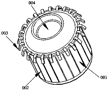
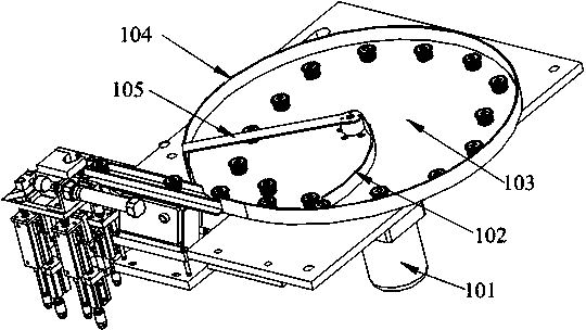
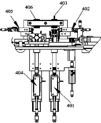
[0029] Such as figure 1 As shown, the commutator automatic detection device includes the machine table and the turntable arranged on the machine table in sequence 1, the inter-chip high-voltage test and high-voltage test device 4, the go-no-go gauge detection device 9, and the copper hook of the commutator is aligned with the slot The detection device 11, the discharge port of the turntable 1 is provided with a linear feeder 2, the discharge end of the linear feeder 2 is provided with a first manipulator 3, and the first manipulator 3 is opposite to the inter-chip high-voltage test and high-voltage test device 4 A high-voltage tester 5 is arranged above the inter-chip high-voltage test and high-voltage test device 4, a conveyor belt 7 is connected next to the inter-chip high-voltage test and high-voltage test device 4, and a second manipulator 8 is provided at the discharge end of the conveyor belt 7, The second manipulator 8 is opposite to the go-no-go gauge detection device ...


PUM


Abstract

The invention relates to an automatic detection device for a commutator. The automatic detection device for the commutator comprises a machine table, a rotating table, an inter-sheet high voltage test and high voltage resistance test device, a stop-pass gauge test device, a commutator brass hook and a groove alignment detection device, the rotating table, the inter-sheet high voltage test and high voltage resistance test device, the stop-pass gauge test device, the commutator brass hook and the groove alignment detection device are arranged on the machine table in sequence, a linear feeder is arranged on the discharging port of the rotating disc, a first mechanical arm is arranged at the discharging end of the linear feeder and is opposite to the inter-sheet high voltage test and high voltage resistance test device, a high voltage testing instrument is arranged above the inter-sheet high voltage test and high voltage resistance test device, a conveying belt is connected beside the inter-sheet high voltage test and high voltage resistance test device, a second mechanical arm is arranged at the discharging end of the conveying belt, the second mechanical arm is opposite to the stop-pass gauge test device, the commutator brass hook and the groove alignment detection device, and a third mechanical arm is arranged beside the commutator brass hook and the groove alignment detection device. Multiple detection processes are achieved on one production line, detection is fully automatic in the whole process, the labor intensity of workers is greatly lowered, cost is lowered, and product quality is stable.

Description

technical field [0001] The invention relates to a device for detecting commutator products, belonging to the technical field of automation equipment. Background technique [0002] At present, the process of commutator product testing process is: firstly, the operator manually takes the product to test the high-voltage resistance on a simple high-voltage tester, and then manually takes the test of the inter-chip pressure in the next process, and all the tests are completed manually , The withstand voltage instrument can withstand high voltage of 10,000 volts, which is dangerous and slow. [0003] When inspecting the inner hole of the product, the products are manually taken one by one and tested with the go-stop gauge. The go-gauge passes and the stop gauge stops. Repeated labor. The same is true for imports, which are time-consuming and difficult to guarantee quality. [0004] The angle detection of the hook is manually put into the jig and pressed in, which is dangerous a...

Claims


Application Information

Patent Timeline
IPC IPC(8): G01D21/02B07C5/36B25J9/02
Inventor 刘健晨胡尧坤
Owner 三笠电器技研(苏州)有限公司
Learn More