A connection terminal for electrical equipment

A technology for connecting terminals and electrical equipment, applied in the direction of conductive connection, electrical component connection, connection, etc., can solve the problems of discharge, long replacement cycle, expensive replacement cost, etc., to solve the problem of air discharge, shielding the interface electric field, and saving maintenance costs. Effect

Active Publication Date: 2015-12-30
成都盛帮双核科技有限公司
View PDF5 Cites 0 Cited by
  • Summary
  • Abstract
  • Description
  • Claims
  • Application Information

AI Technical Summary

Problems solved by technology

[0003] First, since the rubber sleeve and the epoxy resin material layer adopt a set structure, after long-term operation of the equipment, the rubber sleeve and the epoxy resin material layer will age and relax, resulting in insufficient interface pressure between the rubber sleeve and the epoxy resin layer. discharge phenomenon
[0004] Second, the outdoor parts such as rubber bushings and epoxy resin layers are more likely to be damaged or aged. Once the rubber bushing or epoxy resin layer is found to be invalid during the maintenance of external power supply lines or electrical equipment, the electrical equipment box needs to be disassembled , or even replace the entire electrical equipment, resulting in expensive replacement costs and long replacement cycles
[0005] Third, there is no grounding shield inside the existing electrical equipment products such as switches on the pole, and the ground potential is the surface of the electrical equipment box. Phenomena such as air discharge and flashover

Method used


Image

  • A connection terminal for electrical equipment
  • A connection terminal for electrical equipment
  • A connection terminal for electrical equipment

Examples


Embodiment Construction

[0022] In order to make the object, technical solution and advantages of the present invention clearer, the present invention will be described in detail below in conjunction with the accompanying drawings and specific embodiments. It should be understood that the specific embodiments described here are only used to explain the present invention, not to limit the present invention.

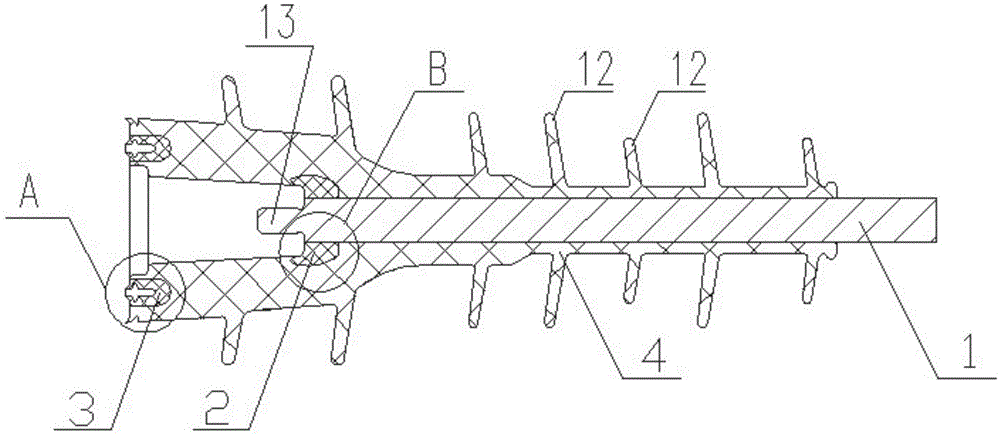
[0023] Such as figure 1 As shown, a connection terminal of electrical equipment is mainly composed of a conductor 1 , a high-voltage shield 2 , a low-voltage shield 3 and an insulator 4 . Wherein, the insulator 4 is made of insulating rubber and is the main body connected to the terminal product. The sheds 12 with larger diameters are distributed on both sides, and these sheds 12 with different diameters are arranged alternately and sequentially on the outer surface of the insulator 4, and the adjacent sheds 12 with different diameters are kept at an appropriate distance ; One end of the insulat...


PUM


Abstract

The invention provides a connection terminal of an electric device. The connection terminal of the electric device mainly comprises a conductor (1), a high-voltage shielding body (2), a low-voltage shielding body (3) and an insulating body (4). The insulating body (4) is a connection terminal body and is of a structure in the shape of an umbrella skirt. One end of the insulating body (4) covers and fixes the conductor (1) and an opened end of an internal cavity of the other end of the insulating body (4) covers and fixes the low-voltage shielding body (3). One end of the conductor (1) is exposed out of the insulating body (4) and the other end of the conductor (1) extends into the cavity of the insulating body (4). The high-voltage shielding body (2) is located at the bottom of the cavity of the insulating body (4) and covers a body of the conductor (1) located in the cavity of the insulating body (4). According to the connection terminal of the electric device, maintenance cost of an external power supply and the electric device which is connected with the external power supply line and a power supply line is saved, the problem of an interface of the electric device is solved and phenomena of air discharge, flashover and the like generated on the joint zone of the electric device and the external power supply line on the surface of the box body of the electrical box are eliminated.

Description

technical field [0001] The invention relates to the field of connection devices between electrical equipment and power supply lines, in particular to a connection terminal of electrical equipment for connecting electrical equipment such as pole-mounted switches and transformers to power supply lines. Background technique [0002] In the prior art, the connection between electrical equipment such as pole-mounted switches and external power supply lines is generally to use the connection conductor protruding from the inside of the electrical equipment box to directly connect to the external power supply line of the box. In order to solve the creepage distance of electrical equipment, For interface problems, epoxy resin material layers and rubber sleeves are usually poured outside the conductors protruding from the inside of the electrical equipment box. The shortcomings of this structure are reflected in the following three aspects: [0003] First, since the rubber sleeve and...

Claims


Application Information

Patent Timeline
Patent Type & Authority Patents(China)
IPC IPC(8): H01R11/00
Inventor 王海鱼范德波张金梅张焕新
Owner 成都盛帮双核科技有限公司
Why Eureka
Try Eureka