Electric cylinder anti-rotation mechanism

An electric cylinder and anti-rotation technology, which is applied in the direction of electric components, electrical components, electromechanical devices, etc., can solve the problems of fast wear of the drive rod and anti-rotation mechanism of the electric cylinder, reduced service life and reliability of the motor, and high load rate of the motor. Achieve the effect of improving reliability and adaptability, small structure size and improving bearing capacity

Inactive Publication Date: 2013-12-11
NO 771 INST OF NO 9 RES INST CHINA AEROSPACE SCI & TECH
View PDF6 Cites 4 Cited by
  • Summary
  • Abstract
  • Description
  • Claims
  • Application Information

AI Technical Summary

Problems solved by technology

However, when the drive rod of the electric cylinder is telescopically moving, the anti-rotation mechanism and the drive rod are always in a state of sliding friction, which leads to problems such as fast wear of the drive rod and the anti-rotation mechanism of the electric cylinder, high load rate of the motor, and high temperature of the motor. , thereby reducing the service life and reliability of the motor

Method used


Image

  • Electric cylinder anti-rotation mechanism
  • Electric cylinder anti-rotation mechanism
  • Electric cylinder anti-rotation mechanism

Examples


Embodiment Construction

[0024] The present invention will be further described in detail below in conjunction with specific examples, which are explanations of the present invention rather than limitations.

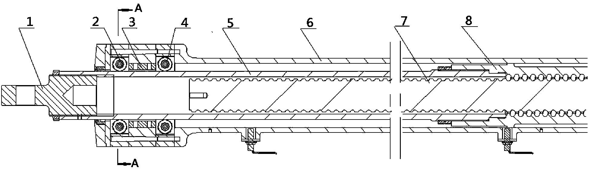
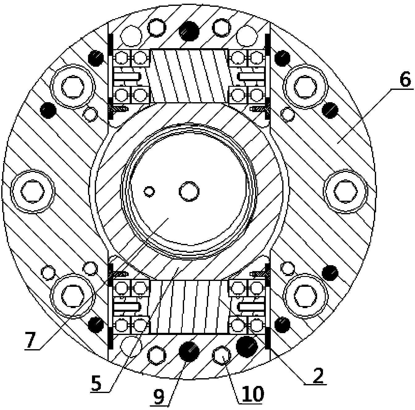
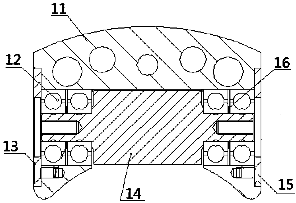
[0025] Such as figure 1 with figure 2 As shown, the present invention is an electric cylinder anti-rotation mechanism, which includes a guide rod 5 threaded with the screw nut 8 of the electric cylinder, and several anti-rotation components; Fixed cage 11, and the roller 14 that is arranged on the cage 11 by rotation; The outer wall of guide rod 5 is provided with anti-rotation plane, and each anti-rotation plane is in rolling contact with at least one roller 14; The centerlines are perpendicular to each other. The setting of anti-rotation planes can be one, two, three or more. In this embodiment, two parallel anti-rotation planes are preferably used as an example. Through the rollers 14 provided in rolling contact on the two anti-rotation planes, one On the one hand, it limits the rotation ...


PUM


Abstract

The invention relates to an electric cylinder anti-rotation mechanism which comprises a guide rod and a plurality of anti-rotation assemblies, wherein the guide rod is in screw-thread fit with a lead screw nut of an electric cylinder. Each anti-rotation assembly comprises a holder and idler wheels, wherein the holder is fixedly connected with a supporting shell of the electric cylinder, and the idler wheels are arranged on the holder in a rotating mode. Anti-rotation planes are arranged on the outer wall of the guide rod, each anti-rotation plane makes rolling contact with at least one idler wheel, and the center lines of the idler wheels are perpendicular to the center line of the guide rod. The rolling contact between the guide rod and the idler wheels is achieved by simultaneously utilizing the idler wheels and the guide rod, wherein the idler wheels and the guide rod are perpendicularly arranged. When the lead screw nut rotates along with a lead screw shaft, the requirement for the anti-rotation function of the guide rod is met through the contact between the idler wheels and the anti-rotation planes, therefore, rotation prevention of the lead screw nut is achieved, and the lead screw nut can do frontward and backward linear movement relative to the lead screw shaft. Under the linear movement, the guide rod makes rolling contact with the idler wheels, sliding friction produced when rotation prevention is achieved in the prior art is avoided, abrasion is reduced, the load rate and the temperature of a motor are lowered, the service life is prolonged, and reliability is improved in the working process.

Description

technical field [0001] The invention relates to the technical field of anti-rotation of electric cylinders, in particular to an anti-rotation mechanism of electric cylinders. Background technique [0002] The reliability and life of the anti-rotation mechanism of the electric cylinder are important indicators for evaluating the reliability and life of the electric cylinder. The internal anti-rotation mechanism has the advantages of compact structure and small volume, and has been widely used in electric cylinders. However, when the drive rod of the electric cylinder is telescopically moving, the anti-rotation mechanism and the drive rod are always in a state of sliding friction, which leads to problems such as fast wear of the drive rod and the anti-rotation mechanism of the electric cylinder, high load rate of the motor, and high temperature of the motor. , thereby reducing the service life and reliability of the motor. At the same time, the anti-rotation mechanism of the...

Claims


Application Information

Patent Timeline
Patent Type & Authority Applications(China)
IPC IPC(8): H02K7/06H02K7/10
Inventor 龚荣文李忠涛曲泓昺
Owner NO 771 INST OF NO 9 RES INST CHINA AEROSPACE SCI & TECH
Why Eureka
Try Eureka