Accumulated charge pump

A technology of boosting charge pump and capacitor, applied in the field of charge pump, can solve the problem that the output cannot meet the requirements

Active Publication Date: 2013-12-11
临沂高新区人才职业培训学校有限公司
View PDF5 Cites 6 Cited by
  • Summary
  • Abstract
  • Description
  • Claims
  • Application Information

AI Technical Summary

Problems solved by technology

Due to the variability of the input voltage, the output

Method used


Image

  • Accumulated charge pump
  • Accumulated charge pump
  • Accumulated charge pump

Examples


Embodiment Construction

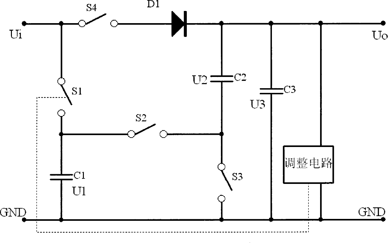
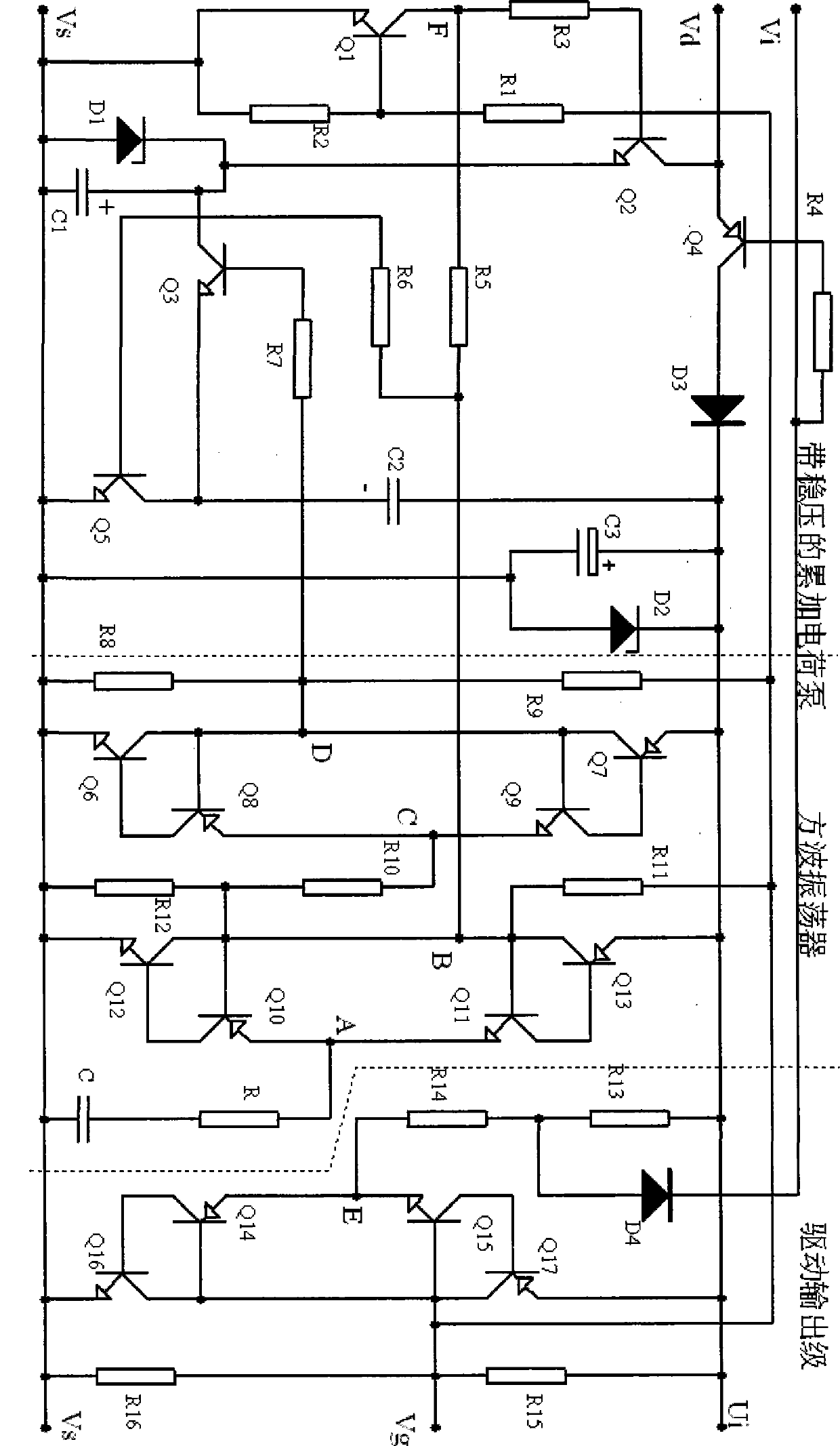
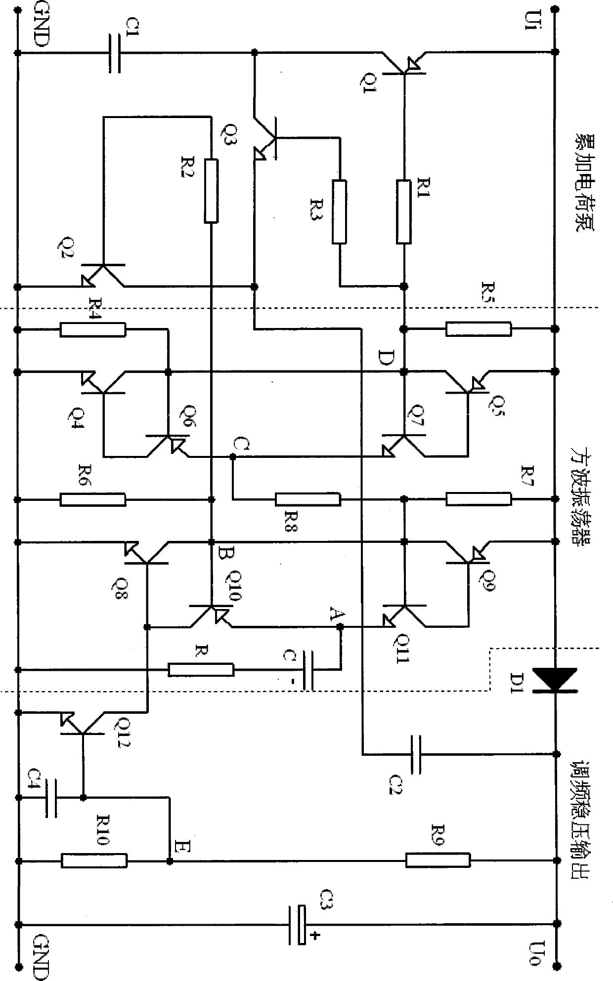
[0011] Application 1. A passive drive circuit for MOSFETs is formed by accumulating charge pumps.

[0012] When the MOSFET is turned off, in order to minimize the leakage current, it is required that the passive drive circuit should stop working when the MOSFET is turned off, and only the charge stored in the capacitor should keep the driven MOSFET turned off; when it is turned on, the driving voltage and current should be established quickly, and It is necessary to provide a continuous drive current to maintain the reliable turn-on of the MOSFET.

[0013] Such as figure 2 It is a driving circuit of N_MOSFET. Vi is the input terminal of the control signal, and Vd, Vs, and Vg are respectively connected to the drain D, source S, and gate G of the MOSFET. figure 2 The dotted line is used to separate three parts: accumulative charge pump with voltage regulation, square wave oscillator, and driver output stage. Among them, the square wave oscillator and the main body of the dr...


PUM


Abstract

The invention relates to an accumulated charge pump, and belongs to the technical field of charge pumps. The boosting aim that an MOSFET passive driving circuit fetches the voltage from a VDS is achieved. After initialization is completed, an S4 and a D1 are cut off due to reversal of biasing of the D1, and a sub-circuit is disconnected. An S1 is closed to buffer a Ui on a C1, meanwhile, an S3 is closed to feed the voltage of an output C3 back to a C2, and an S2 is disconnected in the process. Then the S2 is closed, the S1 and the S3 are simultaneously opened to enable the C2 to be connected with the C1 in series to supply power to the C3, and accumulation of the voltage of the Ui is achieved. After completion of each work cycle, the voltage of each capacitor is that U1=Ui, U2=U3-U1, U3=N*U1+U2, and the N is the switching period number. The accumulated charge pump is applied to the MOSFET passive driving circuit, a low-power boosting type charge pump and the like.

Description

technical field [0001] The technology belongs to the field of charge pump technology. Background technique [0002] In the capacitance matrix of the capacitance source, MOSFETs are used to realize the series-parallel conversion of capacitances. When using active MOSFET driver chips, it is necessary to add power to each driver chip, which makes the application of MOSFETs very inconvenient. The minimum voltage driven by the power MOSFET is not lower than 10V, because the uncertainty of the load current makes the drain-source voltage drop of the MOSFET inconsistent, ranging from a few tenths of volts to two or three volts, different drain-source The voltage drop of the working current is also different. To realize passive MOSFET driving, the voltage of the driving circuit must use a booster circuit to boost the drain-source voltage of the MOSFET to above 10V for the driving circuit to work. Due to the variability of the input voltage, the output cannot be achieved using the e...

Claims


Application Information

Patent Timeline
IPC IPC(8): H02M3/07
Inventor 不公告发明人
Owner 临沂高新区人才职业培训学校有限公司
Why Eureka
Try Eureka