Pre-amplifier circuit of CMOS comparator

A preamplifier and comparator technology, which is applied to DC-coupled DC amplifiers, differential amplifiers, and improved amplifiers to reduce temperature/power supply voltage changes, etc. Pole frequency reduction, etc.

Active Publication Date: 2013-12-11
NORTHWESTERN POLYTECHNICAL UNIV
View PDF3 Cites 5 Cited by
  • Summary
  • Abstract
  • Description
  • Claims
  • Application Information

AI Technical Summary

Problems solved by technology

But the disadvantage of this scheme is that due to the introduction of additional storage capacitor C on the signal path 1 and C 2 , so th

Method used


Image

  • Pre-amplifier circuit of CMOS comparator
  • Pre-amplifier circuit of CMOS comparator
  • Pre-amplifier circuit of CMOS comparator

Examples


Embodiment Construction

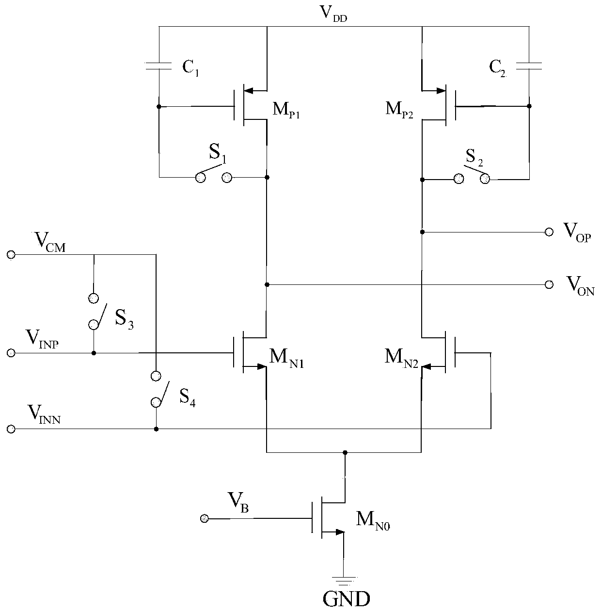
[0012] refer to Figure 1-3 . The preamplifier circuit of the CMOS comparator of the present invention comprises an NMOS transistor M N1 , NMOS transistor M N2 , NMOS transistor M N0 , PMOS transistor M P1 , PMOS transistor M P2 , switch S 1 , switch S 2 , switch S 3 , switch S 4 , storage capacitor C 1and storage capacitor C 2 . NMOS transistor M N1 and NMOS transistor M N2 As a differential input pair; PMOS transistor M P1 and PMOS transistor M P2 As a load, switch S 1 and S 2 respectively connected to the PMOS transistor M P1 and PMOS transistor M P2 Between gate and drain; offset storage capacitor C 1 and offset storage capacitor C 2 One end of each is connected to the PMOS transistor M P1 and PMOS transistor M P2 gate, the offset storage capacitor C 1 and offset storage capacitor C 2 The other end is connected to the power supply V DD superior. NMOS transistor M N1 and NMOS transistor M N2 The gates are respectively connected to the input signa...


PUM


Abstract

The invention discloses a pre-amplifier circuit of a CMOS comparator to solve the technical problem that an existing pre-amplifier circuit operates slowly. According to the technical scheme, an NMOS transistor MN1 and an NMOS transistor MN2 serve as differential input geminate transistors. A PMOS transistor MP1 and a PMOS transistor MP2 serve as loads, and a switch S1 and a switch S2 are connected between a grid electrode and a drain electrode of the PMOS transistor MP1 and between a grid electrode and a drain electrode of the PMOS transistor MP2 respectively. One end of a storage capacitor C1 and one end of a storage capacitor C2 are connected to the grid electrode of the PMOS transistor MP1 and the grid electrode of the PMOS transistor MP2 respectively, and the other end of the storage capacitor C1 and the other end of the storage capacitor C2 are connected to a power source VDD. Due to the fact that the storage capacitor C1 and the storage capacitor C2 are not arranged on a signal channel, the output pole and the bandwidth of a pre-amplifier are not affected, the offset voltage is eliminated, and the operating speed of the pre-amplifier is not affected. Therefore, the pre-amplifier circuit of the CMOS comparator has the advantages of being high in speed and precision.

Description

technical field [0001] The invention relates to a preamplifier circuit, in particular to a preamplifier circuit of a CMOS comparator. Background technique [0002] In electronic information processing systems, high-speed and high-precision analog-to-digital converters are required to convert analog signals to digital signals. The comparator is the core circuit of the analog-to-digital converter, and the speed and precision of the comparator determine the overall performance of the analog-to-digital converter. To increase the accuracy and speed of a comparator, it is usually necessary to take steps to remove the offset voltage of the comparator. [0003] refer to Figure 4 . The document "Behzad Razavi, Principles of Data Convention System Design, pp.201-202" discloses a comparator structure that eliminates output offset voltage. The comparator is composed of a preamplifier and a latch, and the elimination Calibration circuit for preamplifier output offset voltage. Its wo...

Claims


Application Information

Patent Timeline
IPC IPC(8): H03F1/30H03F3/45
Inventor 刘伟魏廷存李博高武郑然胡永才
Owner NORTHWESTERN POLYTECHNICAL UNIV
Why Eureka
Try Eureka