Transformer station optical fiber fault locating system and method

A fiber optic fault and positioning system technology, applied in electromagnetic wave transmission systems, transmission systems, electrical components, etc., can solve problems such as difficult repairs of fiber optic faults, delays in handling accidents, and increased losses

Inactive Publication Date: 2013-12-11
CHONGQING UNIV +2
View PDF2 Cites 36 Cited by
  • Summary
  • Abstract
  • Description
  • Claims
  • Application Information

AI Technical Summary

Problems solved by technology

This technology can effectively monitor the distance between the fault point and the monitoring point, but it cannot display the spatial position (coordinate value) of the fault point. Due to the complicated direction of optical fiber embedding in the power system, this brings great difficulties to the repair of optical fiber faults , and in the actual PFTTH network fiber fault processing, the traditional OTDR cannot meet the requirements of multi-branch, one-way high-loss real-time online monitoring of the access network, and often delay accidents due to the inability to quickly and accurately find the location of the fault point Dealing with situations that lead to increased losses

Method used


Image

  • Transformer station optical fiber fault locating system and method
  • Transformer station optical fiber fault locating system and method
  • Transformer station optical fiber fault locating system and method

Examples


Embodiment Construction

[0053] Embodiments of the present invention are described in detail below, examples of which are shown in the drawings, wherein the same or similar reference numerals designate the same or similar elements or elements having the same or similar functions throughout. The embodiments described below by referring to the figures are exemplary only for explaining the present invention and should not be construed as limiting the present invention.

[0054] In describing the present invention, it should be understood that the terms "longitudinal", "transverse", "upper", "lower", "front", "rear", "left", "right", "vertical", The orientation or positional relationship indicated by "horizontal", "top", "bottom", "inner", "outer", etc. are based on the orientation or positional relationship shown in the drawings, and are only for the convenience of describing the present invention and simplifying the description, rather than Nothing indicating or implying that a referenced device or elem...


PUM


Abstract

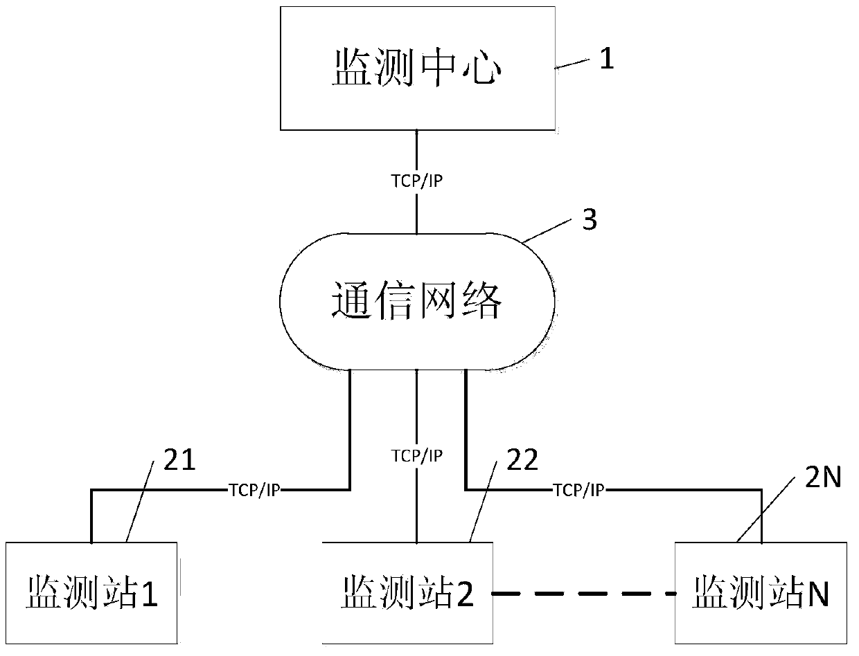
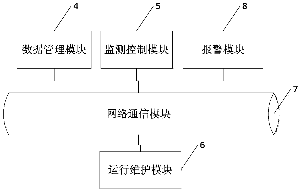
The invention brings forward a transformer station optical fiber fault locating system and method, and relates to the field of optical fiber fault detection. A monitoring center comprises: a data management module, a monitoring control module and an alarm module. The data management module is used for maintaining and managing testing information of the monitoring center itself and testing information and parameter configuration information which are sent by a monitoring station. The monitoring control module is used for managing testing information and parameter configuration information of the monitoring station. Testing information and parameter configuration information of the monitoring station are analyzed and stored. Optical fiber performance information acquired by the monitoring station is sent to the monitoring control module to analyze, and the analyzed testing information, parameter configuration information and optical fiber performance information are judged so that warning information is obtained. Warning information is transmitted to the alarm module which is used for locating warning information via geographical location information pre-stored by the alarm module so that fault location information is displayed.

Description

technical field [0001] The invention relates to the technical field of substation optical fiber communication, in particular to a substation optical fiber fault location system and method. Background technique [0002] Optical fiber communication, as the main transmission mode of the current power system, is more and more widely used. It not only realizes long-distance transmission of signals, but also has stable transmission signal performance. In order to ensure the stability of the line, the network must be well monitored. When the network fails At the same time, if the location of the problematic optical path cannot be effectively found out, it will inevitably cause a lot of time and economic loss. At present, OTDR (Optical Time Domain Reflectometer) technology is mainly used for the location of optical fiber faults. This technology can effectively monitor the distance between the fault point and the monitoring point, but it cannot display the spatial position (coordina...

Claims


Application Information

Patent Timeline
Patent Type & Authority Applications(China)
IPC IPC(8): H04B10/075H04B10/071
Inventor 熊兰刘钰郝海泉李伟罗珊杨子康宋道军姚树友
Owner CHONGQING UNIV
Why Eureka
Try Eureka