Optoacoustic image pick-up system and optoacoustic image pick-up device

A camera system, photoacoustic technology, applied in measuring devices, ultrasonic/sonic/infrasonic diagnosis, solid analysis using sound/ultrasonic/infrasonic, etc. It can solve problems such as difficulty in building vibrator groups and achieve high-speed shooting effects

Inactive Publication Date: 2013-12-11
PANASONIC CORP
View PDF1 Cites 10 Cited by
  • Summary
  • Abstract
  • Description
  • Claims
  • Application Information

AI Technical Summary

Problems solved by technology

However, the construction of such oscillator groups is extremely difficult

Method used


Image

  • Optoacoustic image pick-up system and optoacoustic image pick-up device
  • Optoacoustic image pick-up system and optoacoustic image pick-up device
  • Optoacoustic image pick-up system and optoacoustic image pick-up device

Examples


no. 1 approach

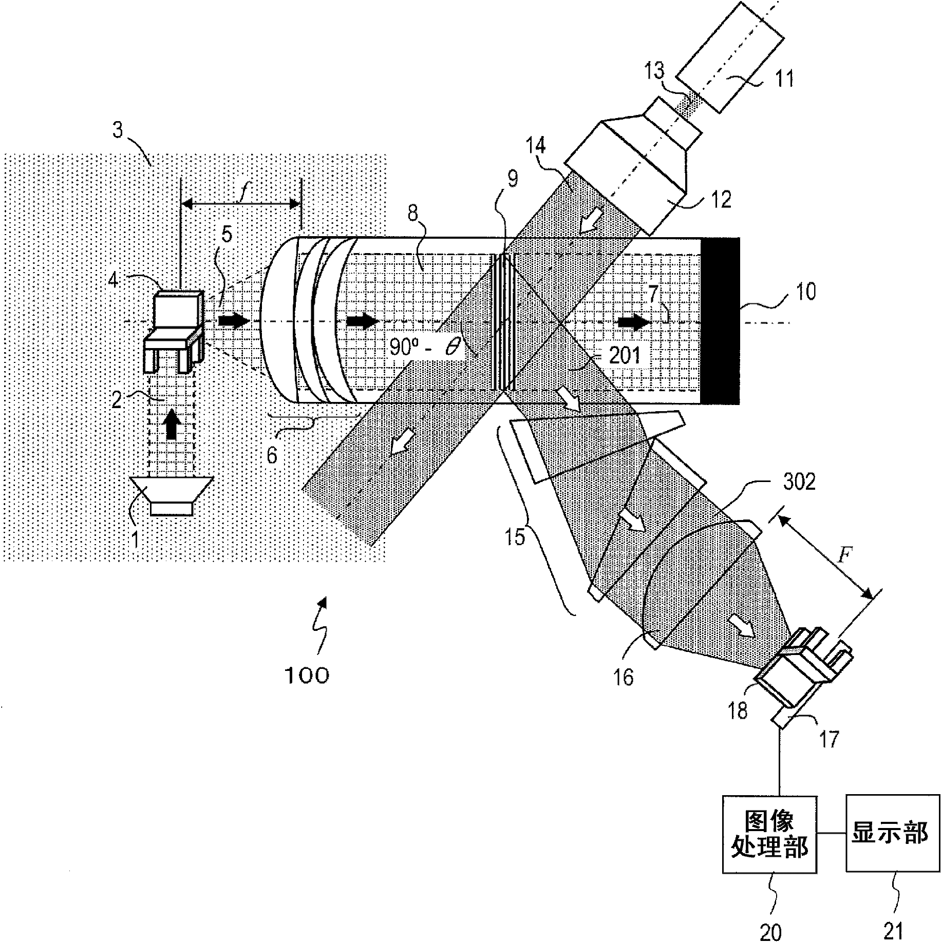
[0060] figure 1 It is a diagram schematically showing the configuration of the photoacoustic imaging system 100 according to the first embodiment of the present invention. The photoacoustic imaging system 100 includes an ultrasonic wave source 1, a photoacoustic medium 8, an acoustic lens 6 disposed on the surface of the photoacoustic medium 8 on the side of the object 4, and an acoustic lens 6 disposed on the surface of the photoacoustic medium 8 facing the surface on which the acoustic lens 6 is disposed. The acoustic wave absorbing end 10 , the monochromatic light source 11 , the beam expander 12 , the distortion correcting part 15 , the imaging lens 16 and the image receiving part 17 are arranged on the surface. and also, figure 1 The illustrated subject 4 and image 18 are not components of the photoacoustic imaging system 100 and are shown for convenience of description.

[0061] The ultrasonic wave source 1 , the acoustic lens 6 , a part of the photoacoustic medium 8...

Embodiment approach 2

[0131] Next, a second embodiment of the present invention will be described.

[0132] Figure 8 It is a figure showing the structure of the acoustic lens 60 of the photoacoustic imaging system 200 of this embodiment. The only difference between the photoacoustic imaging system 200 of this embodiment and the photoacoustic imaging system 100 of Embodiment 1 is the configuration of the acoustic lens. Therefore, descriptions of components other than the acoustic lens 60 of the photoacoustic imaging system 200 are omitted.

[0133] In the photoacoustic imaging system 100 according to Embodiment 1, both the acoustic lens 6 and the photoacoustic medium 8 are made of nanoporous silica. It was demonstrated that the sound velocity of the porous silica body can be varied in a wide range by adjusting the preparation conditions of the nanoporous silica body. Therefore, by using the silica nanoporous body as the acoustic lens 6, flexible selection of the acoustic medium is possible. Lik...

no. 3 approach

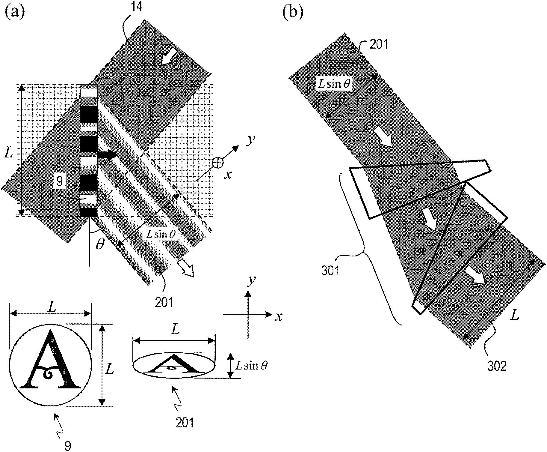
[0141] Figure 9 It is a diagram showing a configuration example of the distortion correcting unit 15 of the photoacoustic imaging system according to the present embodiment. The difference between this embodiment and Embodiments 1 and 2 is only the configuration of the distortion correcting unit 15 . Therefore, descriptions of components other than the distortion correcting unit 15 are omitted.

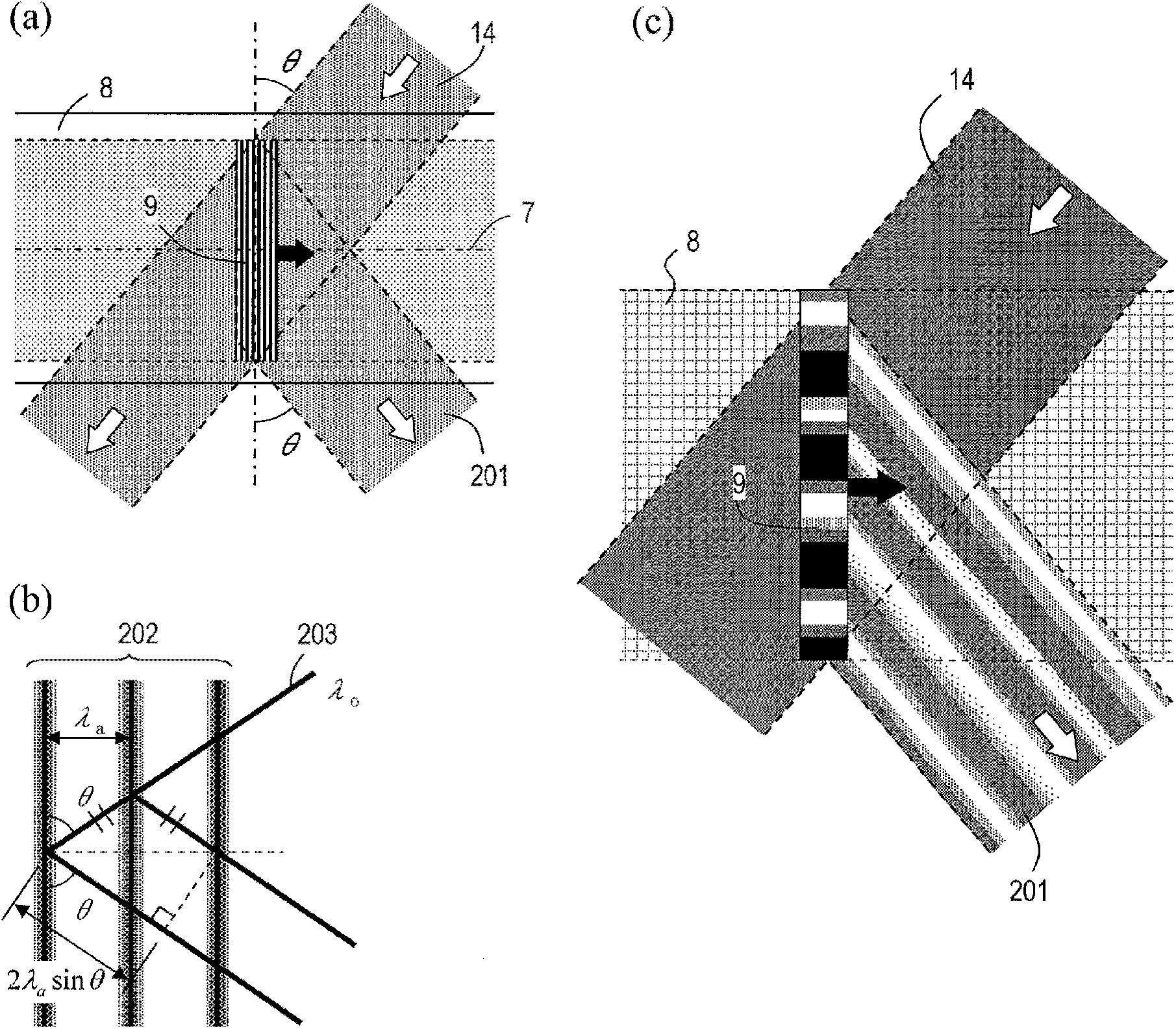
[0142] Such as image 3 As shown, when the diffraction angle is set to θ, the diffracted light 201 generated by Bragg diffraction is compared with image 3 In the direction parallel to the paper surface (y-axis direction), it shrinks to sinθ times. Therefore, if the diffracted light 201 is directly imaged by the imaging lens 6, the image 18 will be distorted and an image similar to the subject 4 cannot be obtained. The function of the distortion correcting part 15 is, in order to solve this problem, make the diffracted light 201 image 3 The direction parallel to the paper surfa...


PUM


Abstract

In the present invention, an optoacoustic image pick-up system is provided with the following: an ultrasonic wave wave source (1) for projecting to a subject of image pick-up (4) ultrasonic waves formed by an acoustic signal having temporal waveforms that are repeated at a predetermined time interval; an acoustic lens (6) that is disposed so as to receive the scattered waves of ultrasonic waves (2) projected onto the subject of image pick-up (4) and that converts the scattered waves to plane waves; a translucent acoustic medium (8) provided in a region including a light axis (7) of the acoustic lens (6), the region being on the opposite side of the acoustic lens (6) from the subject of image pick-up (4); a light source (11) that emits single color light plane waves and that is disposed so that the advancing direction of the single color light plane waves and the light axis (7) of the acoustic lens (6) intersect at an angle other than 90 degrees and 180 degrees; an image forming lens (16) disposed so as to focus the diffraction light (201) of the single color light plane waves that was generated within the translucent acoustic medium (8); an image receiving unit (17) that acquires an optical image (18) formed by the image forming lens (16) as image information; and a distortion compensation unit (15) that corrects the distortion of the optical image (18) or the distortion of the image generated from the image information.

Description

technical field [0001] The present application relates to a photoacoustic imaging system, which irradiates an object with ultrasonic waves, guides the ultrasonic waves scattered by the object into the photoacoustic medium to form a refractive index distribution in the photoacoustic medium, and Bragg diffraction ( Also known as Bragg diffraction), the intensity / phase distribution of scattered ultrasonic waves is transferred to the intensity / phase distribution of monochromatic light, and an ultrasonic image is captured as an optical image. Background technique [0002] An ultrasonic diagnostic apparatus is known as an apparatus that irradiates an object with ultrasonic waves and generates an optical image using scattered waves from the object. For example, Patent Document 1 discloses an example of an ultrasonic diagnostic apparatus. [0003] Figure 13 It is a diagram showing the imaging principle of the ultrasonic diagnostic apparatus described in Patent Document 1. Figure ...

Claims


Application Information

Patent Timeline
Patent Type & Authority Applications(China)
IPC IPC(8): A61B8/00G01N29/00
CPCG01N29/221G01N29/2418A61B5/0097G01N29/0681G01N29/46G01N29/04
Inventor 寒川潮岩本卓也金子由利子桥本雅彦
Owner PANASONIC CORP
Why Eureka
Try Eureka