
Dust collection filter, dust collection apparatus provided with same, and manufacturing method for dust collection filter

A filter and dust collection technology, applied in membrane filters, chemical instruments and methods, filtration and separation, etc., can solve the problems of not forming, increasing the number of dusting, not functioning as a telescopic filter layer, etc., and achieves a good yield, Create relaxing effects

Active Publication Date: 2013-12-11
NIHON SPINDLE MFG CO LTD
View PDF7 Cites 12 Cited by
  • Summary
  • Abstract
  • Description
  • Claims
  • Application Information

AI Technical Summary

Problems solved by technology

At this time, even if the filter for dust collection is vibrated or stretched, since the displacement in the surface direction (circumferential direction) of the filter layer is restricted by the weft yarn, active expansion and contraction in the surface direction (circumferential direction) of the filter layer is not achieved. The role of layers
That is, there is no structure capable of positively displacing to the filter surface side (tube diameter side) of the dust collection filter
[0009] And, when this kind of filter for dust collection is applied to the dust collector shown in Patent Document 2 and used, although it is possible to shake off the dust collected on the filter surface of the filter for dust collection by passing through the countercurrent airflow, However, as mentioned above, since the filter layer does not actively expand and contract in the direction of the surface, it is difficult to effectively shake off the dust that enters the inside of the filter for dust collection.
[0010] And, as in the above-mentioned dust collector, since the dust-off efficiency of the dust entering the inside of the dust-collecting filter cannot be improved, the average pressure loss based on the dust-collecting filter gradually increases, and the pressure of the countercurrent airflow increases or increases. Due to the need for the frequency of dusting, etc., it becomes a dust collector that cannot achieve energy saving and filter life improvement.

Method used


Image

  • Dust collection filter, dust collection apparatus provided with same, and manufacturing method for dust collection filter
  • Dust collection filter, dust collection apparatus provided with same, and manufacturing method for dust collection filter
  • Dust collection filter, dust collection apparatus provided with same, and manufacturing method for dust collection filter

Examples


Embodiment 1

[0096] Examples 1 and 2 are cases in which the warp yarns 20a and weft yarns 20b in the base fabric layer 20 are arranged obliquely with respect to the cylinder axis direction X of the filter cloth P, that is, the dust collection filter composed of the offset base fabric layer 20 is used. In the case of the device F, embodiment 1 is a situation in which tension is not provided by the hammer body 54, and embodiment 2 is a situation in which tension is provided by the hammer body 54.

[0097] In addition, Comparative Examples 1 and 2 use conventional dust-collecting filters in which the warp yarns 20a and weft yarns 20b in the base fabric layer 20 are in the cylindrical circumferential direction Y and cylindrical axial direction X of the filter cloth P (that is, in a regular lattice shape). In the case of comparative example 1, the tension is not provided by the hammer, and the comparative example 2 is the tension is provided by the hammer.

[0098] In each of the above-describe...


PUM


Abstract

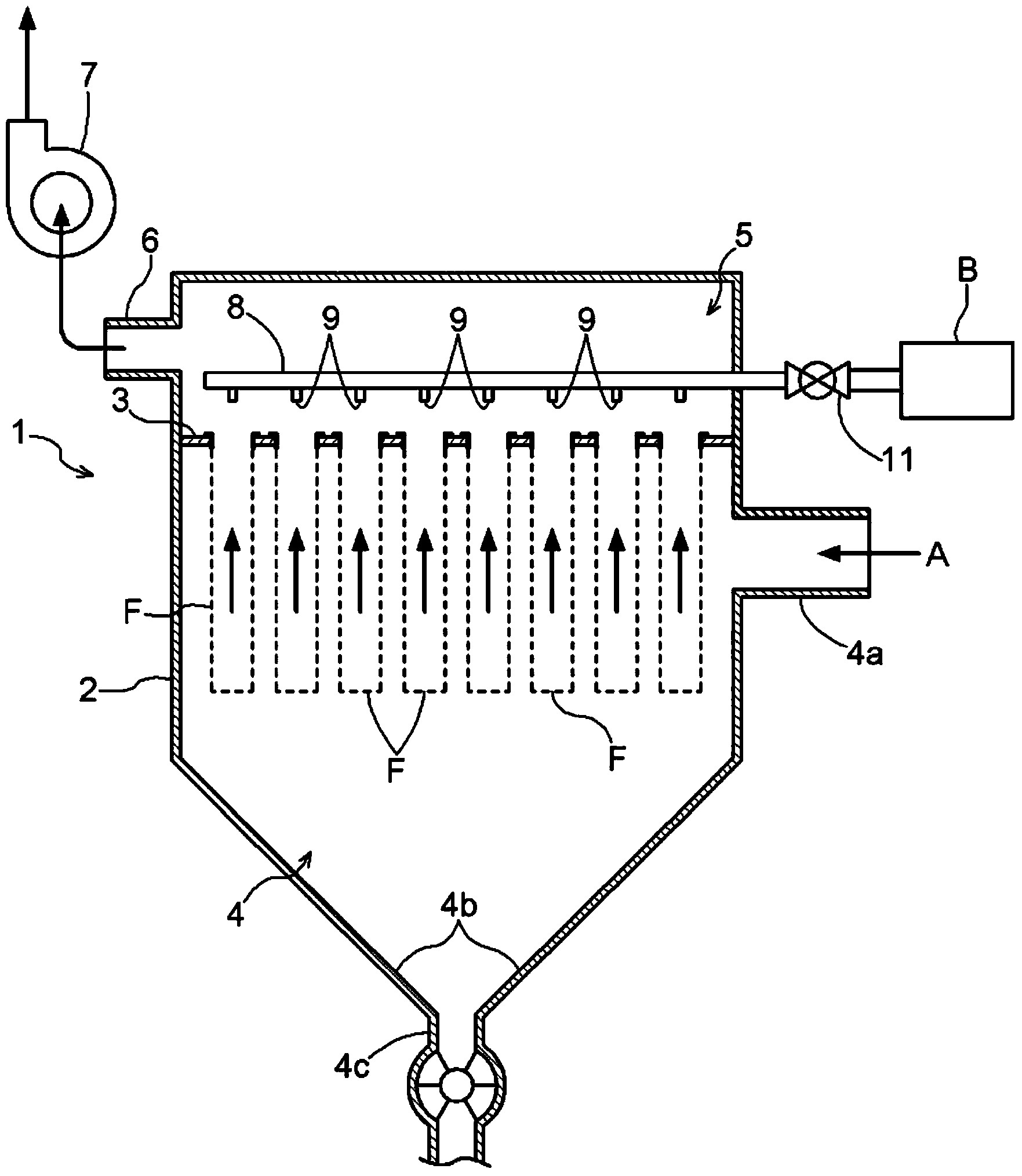
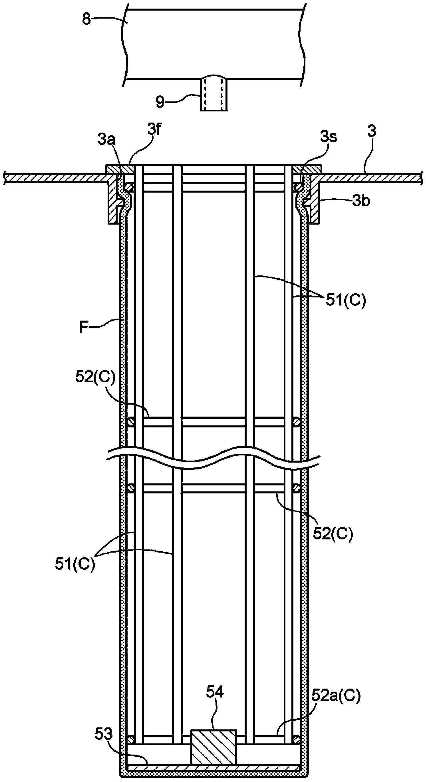
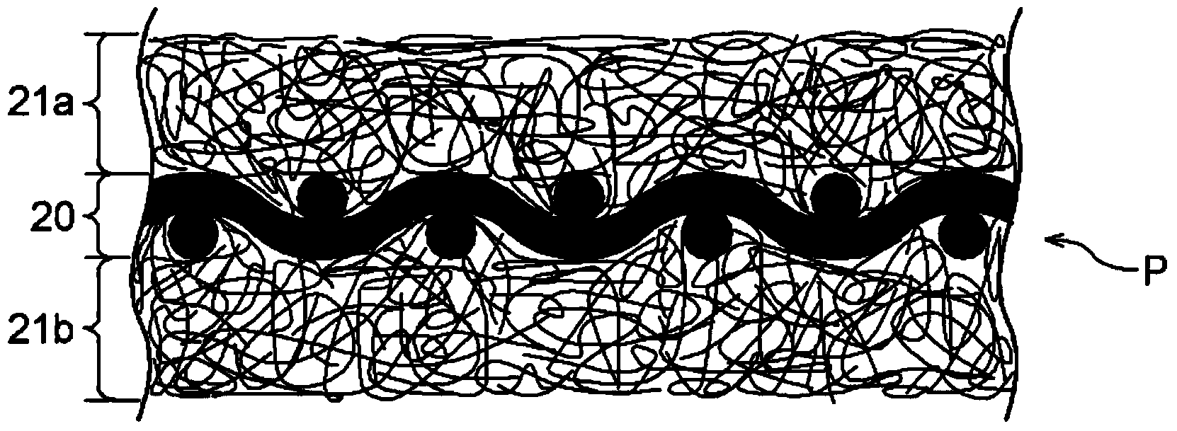
The present invention provides a dust collection filter capable of reducing power usage by reduction of the average pressure loss of the dust collection filter and extending the filter life by improving efficiency of dust removal at the time of recycling a dust collection filter, and provides also a dust collection apparatus provided with the same. A tubular-shaped filtering fabric (P) has a configuration in which are layered: a base fabric layer (20) comprising a woven fabric; and a filter layer comprising a non-woven fabric combined with at least the filtering front surface side of the base fabric layer (20). A dust collection filter (F) is configured to filter dust containing air by passing the same through the filtering fabric (P) from the filtering front surface side to the filtering rear surface side and to remove the dust captured and collected by passing a counter current of air (H) through the filtering fabric (P) from the filtering rear surface side to the filtering front surface side. In the dust collection filter (F), either warps (20a) or woofs (20b) constituting the woven fabric of the base fabric layer (20) are disposed to be slanted to the tubular circumference direction (Y) of the tubular-shaped filtering fabric (P).

Description

technical field [0001] The present invention relates to a filter for dust collection, a dust collection device provided with the filter for dust collection, and a method for manufacturing the filter for dust collection, wherein the filter for dust collection is constituted by laminating woven fabrics The base cloth layer and the filter layer made of non-woven fabric combined at least on the filter surface side of the base cloth layer to form a cylindrical filter cloth, so that the dusty air is filtered from the filter surface side of the filter cloth Filtering is performed by passing the back side, and the collected dust is shaken off by passing a countercurrent airflow from the filter back side of the filter cloth to the filter surface side. Background technique [0002] As a filter for dust collection in a dust collector, the filter (bag filter) which formed the filter cloth in the form of a cylinder is used in many cases. As the filter cloth, a filter cloth formed in a l...

Claims


Application Information

Patent Timeline
Patent Type & Authority Applications(China)
IPC IPC(8): B01D39/16B01D46/02
CPCB01D46/02B01D39/08B01D39/14B01D46/04B01D2239/065B01D2239/0659B01D2275/10B01D46/71B01D46/06
Inventor 木岛敬昌卯山贞信松田承真
Owner NIHON SPINDLE MFG CO LTD
Learn More