
Slaughtering device

The technology of a rotating disk and a base is applied in slaughtering devices, slaughtering devices, devices for restraining livestock to be slaughtered, etc., which can solve the problems of high labor intensity of staff, difficulty in draining the blood of livestock, and not belonging to the category of live killing, etc. Achieve the effects of low machining accuracy and installation accuracy, as well as low center distance accuracy, improved rotational flexibility, and light surface wear of gear teeth

Inactive Publication Date: 2013-12-18
NANJING RESISTANCE HOP SLAUGHTER MACHINERY MFG
View PDF6 Cites 7 Cited by
  • Summary
  • Abstract
  • Description
  • Claims
  • Application Information

AI Technical Summary

Problems solved by technology

[0004] Slaughtering livestock is a very troublesome thing that requires the participation of multiple people and cooperation to complete it. This is not only labor-intensive and time-consuming, but the slaughtering efficiency is extremely low, and the labor intensity of the staff in the slaughterhouse is very high.
In order to reduce the labor intensity of the staff, in many slaughterhouses, animals are usually stunned by electric shock before slaughtering. It is difficult to drain the blood in the animal's body when it is slaughtered in a comatose state, which will affect the quality of the meat, and this method of slaughter does not belong to the category of live killing, and the public often does not accept this kind of meat

Method used


Image

  • Slaughtering device
  • Slaughtering device
  • Slaughtering device

Examples


Embodiment Construction

[0048] In order to make the object, technical solution and advantages of the present invention clearer, the present invention will be further described in detail below in conjunction with the accompanying drawings and embodiments. It should be understood that the specific embodiments described here are only used to explain the present invention, not to limit the present invention.

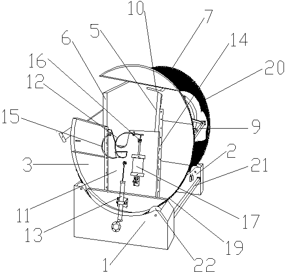
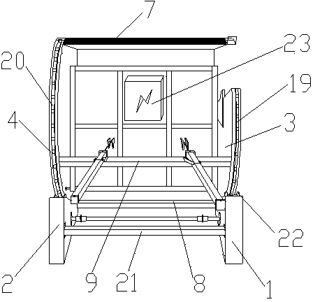
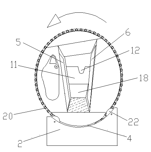
[0049] In a preferred embodiment of the present invention, as figure 1 As shown, it includes a base, a cage, a drive mechanism and a total control box 23 for controlling each cylinder and drive mechanism; wherein, the base is composed of a first base 1 and a second base 2 connected to each other by a connecting rod 21, Both the tops of the first base 1 and the second base 2 are arc-shaped indentations, and a nylon disc 22 is arranged in the indentation, and the first rotating disc 3 and the second rotating disc 4 communicate with the nylon disc 22 respectively. The first base 1 and the second base...


PUM


Abstract

The invention discloses a slaughtering device which comprises a base, a driving mechanism and an imprisoning tank. The imprisoning tank comprises a first rotating table, a second rotating table, a first splint, a second splint, a top cover, a bottom plate and a neck pressure plate; the first rotating table is provided with a neck clamping mechanism and a turnover mechanism; the neck clamping mechanism comprises a neck clamping door and a neck clamping cylinder; the upper part of the neck clamping door is provided with a neck placement concave cavity and the neck placement concave cavity is in slide fit with two parallel guide rails arranged on the first rotating table; the turnover mechanism comprises a fixture and a fixture cylinder; the neck pressure plate is positioned above the first rotating table and the length direction of the neck pressure plate is vertical to the moving direction of the neck clamping door; the driving mechanism comprises a transmission shaft; both a first chain and a second chain are in transmission connection with the transmission shaft; and the transmission shaft is also sequentially connected with a speed reducer and a motor. The slaughtering device provided by the invention has a simple structure and high slaughtering efficiency; labor intensity and cost of workers can be reduced; and the slaughtering device has a high safety coefficient and long service life and is also beneficial for showing live killing and ensuring meat quality of beasts.

Description

[0001] technical field [0002] The invention relates to the field of livestock slaughtering machinery, in particular to a slaughtering device. [0003] Background technique [0004] Slaughtering livestock is a very troublesome thing that requires the participation of multiple people and cooperation to complete it. This is not only labor-intensive and time-consuming, but also the slaughter efficiency is extremely low, and the labor intensity of the staff in the slaughterhouse is very high. In order to reduce the labor intensity of the staff, in many slaughterhouses, animals are usually stunned by electric shock before slaughtering. It is difficult to drain the blood in the animal's body when it is slaughtered in a comatose state, which will affect the quality of the meat. Moreover, such a slaughter method does not belong to the category of live killing, and the public often does not accept this kind of meat. [0005] Contents of the invention [0006] The technica...

Claims


Application Information

Patent Timeline
IPC IPC(8): A22B1/00A22B3/00
Inventor 陈春根孙全龙水白清杨小秋魏广华
Owner NANJING RESISTANCE HOP SLAUGHTER MACHINERY MFG
Learn More