Rubber injection gun

A technology for glue injection guns and hoses, applied in the field of glue injection guns, which can solve the problems of affecting work efficiency, laborious extrusion and injection of glue, upward warping of the push rod and even deformation, and achieves the effect of simple structure

Inactive Publication Date: 2013-12-18
GAOMI ANNAI RUBBER
View PDF0 Cites 5 Cited by
  • Summary
  • Abstract
  • Description
  • Claims
  • Application Information

AI Technical Summary

Problems solved by technology

Existing glue injection guns include a rubber hose bracket and a support frame that are fixed together. A push rod is slidingly connected to the rubber hose bracket and the support frame. The push rod is driven by a handle connected to the support frame. Since the above sliding connection adopts The following structure is realized, that is, a through hole is correspondingly opened at the rear end of the rubber hose bracket and the support frame, and the push rod slides in translation in the through hole. When the handle drives the push rod forward, the top of the push rod will lean against the through hole. There is translational friction on the top wall, so the push is laborious. When pushing the push rod hard to increase the extrusion speed and force, the push rod will often rise up and even cause deformation, which increases the extrusion resistance and makes the extrusion injection difficult. The glue is very laborious, which affects the work efficiency and also affects the service life of the glue gun

Method used


Image

  • Rubber injection gun
  • Rubber injection gun

Examples


Embodiment Construction

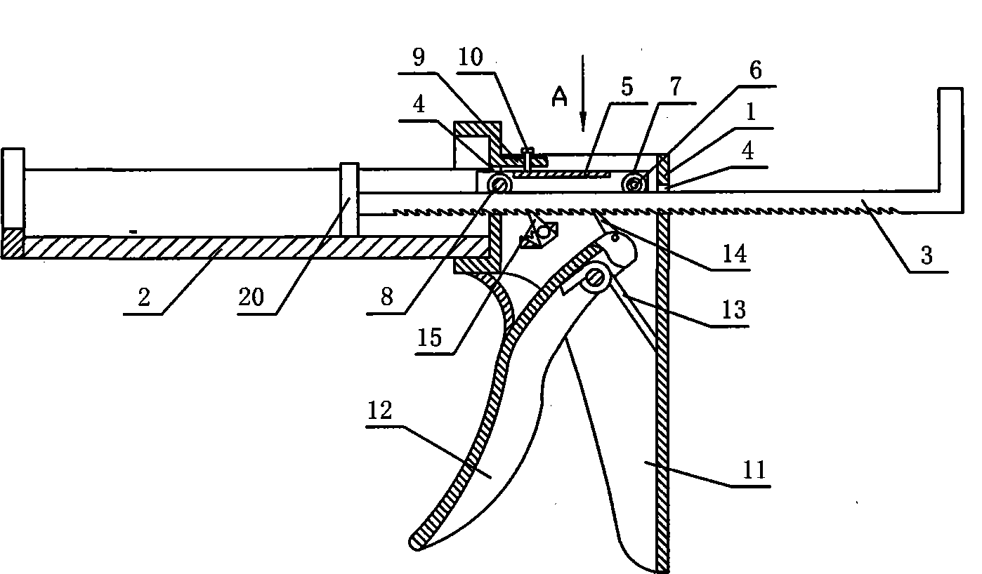
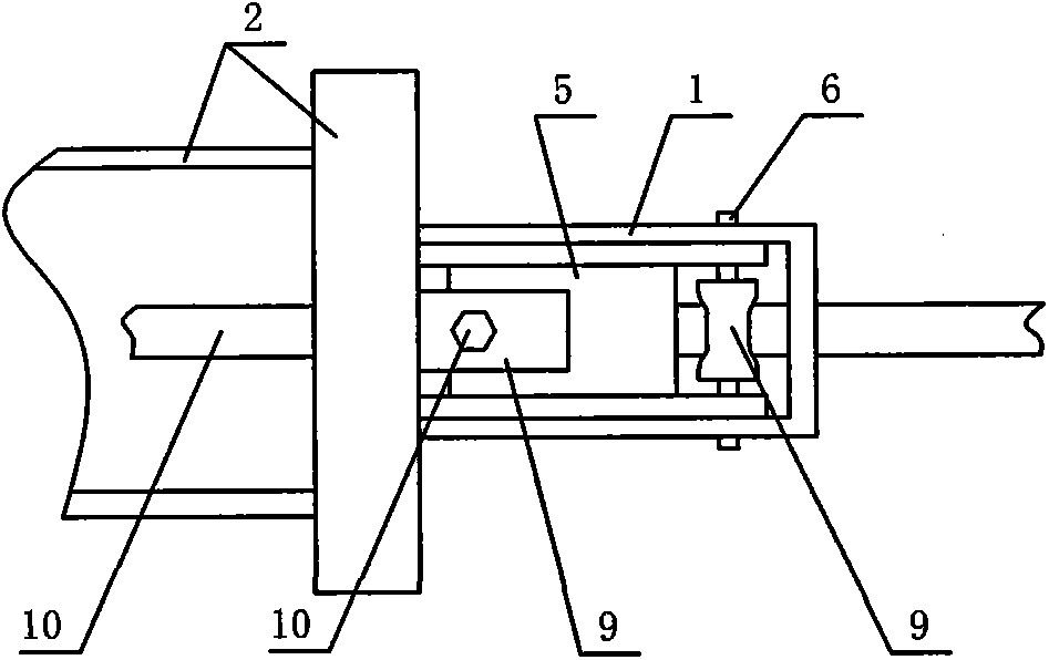
[0012] like figure 1 The glue injection gun shown includes a support frame 1 and a rubber hose bracket 2 connected to the front end of the support frame 1. The rear part of the rubber hose bracket 2 and the support frame 1 is correspondingly provided with a through hole 4, and the through hole 4 is equipped with a push Rod 3, the front part of the push rod 3 is fixed with a push plate 20 sliding along the rubber hose bracket 2, the push rod 3 is driven by the drive mechanism connected to the support frame 1, and the drive mechanism includes a drive mechanism connected to the lower part of the rear end of the support frame 1 Fixed handle 11, fixed handle 11 is hinged with movable handle 12, is provided with torsion spring 13 that is connected on the hinged shaft between fixed handle 11 and movable handle 12, is provided with from front on the surface of push bar 3 The tooth lines arranged backwards, the upper extension end of the movable handle 12 is hinged with the driving too...


PUM


Abstract

The invention discloses a rubber injection gun. The rubber injection gun comprises a support frame and a rubber tube bracket connected at the front end of the support frame, wherein through holes are correspondingly formed at the rear of the rubber tube bracket and the support frame; a push rod penetrates through the through holes; a propelling disc sliding along the rubber tube bracket is fixedly installed on the front of the push rod; the push rod is driven by a driving mechanism connected on the support frame; a guide frame is installed on the support frame; the rear of the guide frame is connected on the support frame via a hinge axis; a rear idler wheel pressing against the top of the push rod is installed on the hinge axis; the front of the guide frame penetrates through the rear end of the rubber tube bracket and is connected with a front idler wheel pressing against the push rod in a rotary manner; the front of the support frame or the rubber tube bracket is connected with a height limiting device for limiting the front height of the guide frame. The rubber injection gun has a simple structure and has the advantages that the rubber injection gun saves effort during pushing and can effectively prevent the push rod from tilting.

Description

technical field [0001] The invention relates to a glue injection gun used for extruding sealant in a rubber hose. Background technique [0002] In the construction of door and window sealants, glue injection guns are used to squeeze the rubber hoses to inject glue. Existing glue injection guns include a rubber hose bracket and a support frame that are fixed together. A push rod is slidingly connected to the rubber hose bracket and the support frame. The push rod is driven by a handle connected to the support frame. Since the above sliding connection adopts The following structure is realized, that is, a through hole is correspondingly opened at the rear end of the hose bracket and the support frame, and the push rod slides in translation in the through hole. When the handle drives the push rod forward, the top of the push rod will lean against the through hole. There is translational friction on the top wall, so the push is laborious. When pushing the push rod hard to incre...

Claims


Application Information

Patent Timeline
Patent Type & Authority Applications(China)
IPC IPC(8): B05C17/005B05C17/10
Inventor 李军
Owner GAOMI ANNAI RUBBER
Why Eureka
Try Eureka