Resin-sealing molding apparatus

A technology of resin sealing and components, which is applied in the direction of electrical components, semiconductor/solid-state device manufacturing, circuits, etc., can solve the problems of product quality degradation, lower sliding properties of frame components and bottom surface components, and limitation of package thickness, etc., to improve freedom degree of effect

Active Publication Date: 2013-12-18
TOWA
View PDF6 Cites 11 Cited by
  • Summary
  • Abstract
  • Description
  • Claims
  • Application Information

AI Technical Summary

Problems solved by technology

The melted resin that enters the gap hardens to form resin burrs, reducing the sliding properties between the frame member and the bottom surface member.
In addition, there are also cases where the resin burrs enter the mold cavity during the release step (demolding step), and are mixed into the product (compression-molded package) during the subsequent compression step (this is referred to as "Pressing of burr"), which reduces the quality of the product
[0007] (2) In the existing known resin sealing molding device, the mold is closed and the molten resin 72 in the cavity is pressurized by one driving source, so the moving distance of the bottom surface member in the frame member is limited to the elastic member within the deformable range
Therefore, the depth of the cavity when compressing the resin is limited, and the thickness of the compression-molded package is limited
[0008] (3) In the conventional resin sealing molding apparatus, when the pressing member is moved downward after the compression molding is completed, the force of the frame member to press the substrate to the upper mold is weak
Moreover, as described above, since there is a burr in the gap between the frame member and the bottom member, the two members of the frame member and the bottom member further move downward integrally, so the compression-molded package cannot be stably released ( demoulding)

Method used


Image

  • Resin-sealing molding apparatus
  • Resin-sealing molding apparatus
  • Resin-sealing molding apparatus

Examples


Embodiment 1

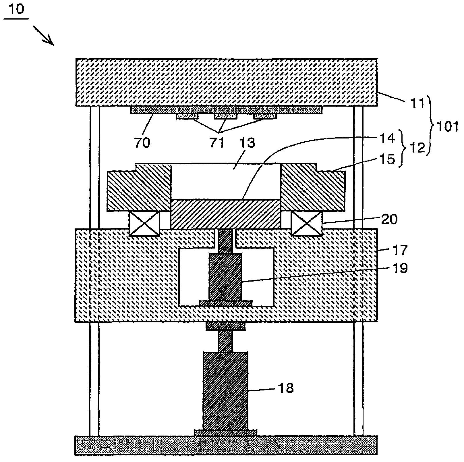
[0059] Below, refer to figure 1 ˜ FIG. 5 describe a first embodiment of the resin sealing molding apparatus for electronic components according to the present invention. The resin sealing molding device 10 of the present embodiment is as figure 1 As shown, it is equipped with: a resin sealing molding mold 101, which is composed of an upper mold 11 that holds a substrate 70 on which electronic components 71 such as semiconductor chips are mounted on the lower surface, and a lower mold 12 that is arranged opposite to the upper mold 11; The member 17 places the lower mold 12 and moves in the vertical direction. The pressing member 17 is driven vertically by a first drive mechanism 18 provided below the pressing member 17 .

[0060] The lower mold 12 is composed of a frame member 15 and a bottom member 14 that can slide up and down in the frame member 15, and can accommodate resin material in the space (cavity 13) surrounded by the frame member 15 and the bottom member 14. He...

Embodiment 2

[0070] Second, refer to Figure 6 ~ Figure 9 A second embodiment of the resin sealing molding apparatus for electronic components of the present invention will be described. The resin sealing molding apparatus 30 of this embodiment moves the frame member 15 up and down by the second drive mechanism 19 . The frame member 15 is connected to a connection member 32 , and the connection member 32 is connected to a frame-shaped movable plate 31 via an elastic member 33 . The movable plate 31 moves up and down by the second driving mechanism 19 placed inside the pressing member 17 ( Image 6 ). Other composition and figure 1 Similarly, the pressing member 17 is driven vertically by a first drive mechanism 18 (not shown) provided below the pressing member 17 .

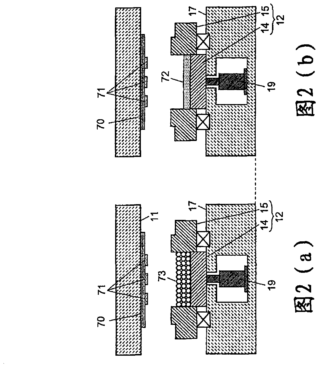
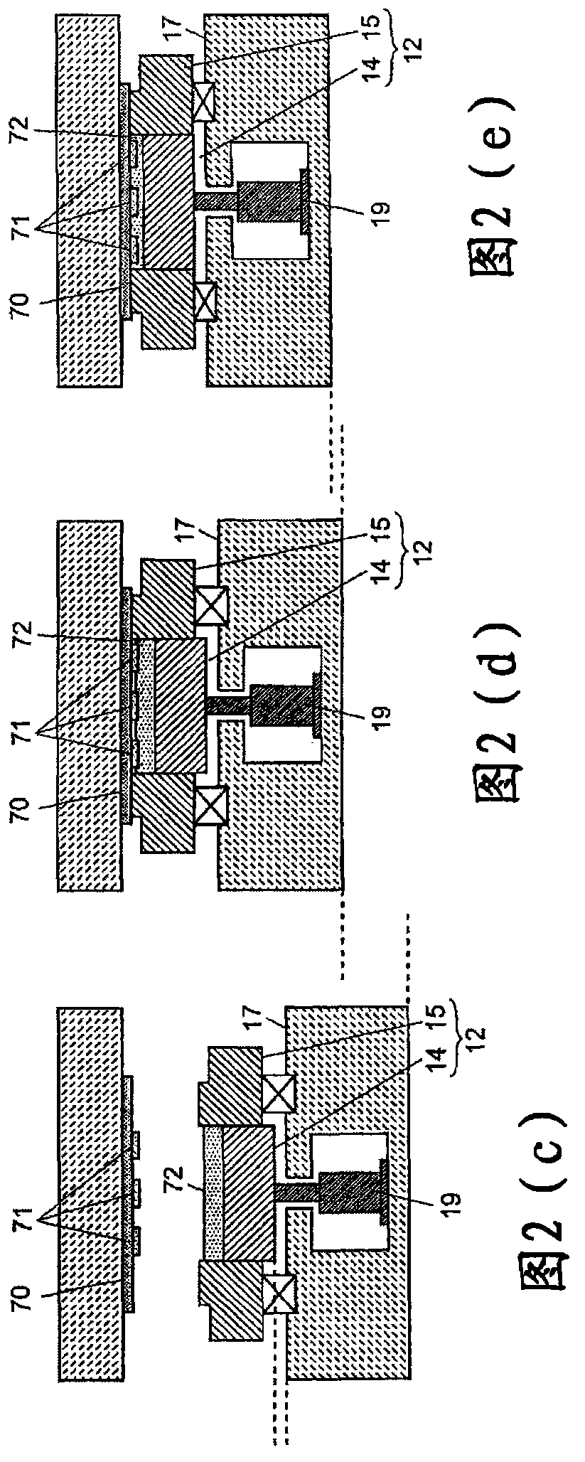
[0071] The steps of resin sealing of electronic components using the resin sealing molding apparatus 30 described above will be described. First, as shown in FIG. 7( a ), the resin sealing mold 101 is opened, and the sub...


PUM


Abstract

The invention provides a resin-sealing molding apparatus, capable of cleaning resin fur penetrated through a gap between a frame component and a bottom component. The lower surface of the resin-sealing molding apparatus is provided with an upper die of an electronic part mounting substrate and a lower die, oppositely disposed with the upper die. The resin-sealing molding apparatus is characterized in that the resin-sealing molding apparatus comprises a frame component which is disposed on a pressurizing component driven up and down by means of a first driving mechanism through an elastic component, and a bottom component which can be driven in an up-and-down sliding manner in the frame component by means of a second driving mechanism.

Description

technical field [0001] The present invention relates to a resin sealing molding device for resin sealing electronic components mounted on a substrate. Background technique [0002] Conventionally, resin sealing and compression molding of electronic components such as semiconductor chips mounted on a substrate has been performed using a resin sealing molding apparatus including a compression molding mold composed of upper and lower molds (for example, refer to Patent Document 1). [0003] An example of a resin sealing molding apparatus used for such resin sealing compression molding is shown in Figure 11 . Figure 11 The resin sealing molding apparatus 50 includes a compression molding mold composed of an upper mold 51 and a lower mold 52 . The upper mold 51 is fixed at a predetermined position on the upper side of the device 50 , and holds the substrate 70 on which the electronic component 71 is mounted on the lower surface. The lower die 52 is composed of a frame member 5...

Claims


Application Information

Patent Timeline
Patent Type & Authority Applications(China)
IPC IPC(8): B29C43/18H01L21/56
Inventor 高濑慎二高丈明田村孝司
Owner TOWA
Why Eureka
Try Eureka