Pneumatic torque-adjustable cap screwing device capable of flexibly clamping

A flexible clamping and pneumatic technology, applied in the direction of threaded bottle caps, etc., can solve the problems of uncontrollable clamping force, screw cracking of bottle caps, and uncontrollable capping torque.

Inactive Publication Date: 2013-12-18
JIANGSU JINWANG PACKING SCI TECH CO LTD
View PDF0 Cites 8 Cited by
  • Summary
  • Abstract
  • Description
  • Claims
  • Application Information

AI Technical Summary

Problems solved by technology

Although the belt screw cap can flexibly rotate the bottle cap without damaging the bottle cap, but with the elongation of the belt, the clamping force of the belt on the bottle cap is unstable and uncontrollable. If the screw is not tight or the screw is too tight, the bottle cap will be cracked, and the torque of the screw cap cannot be controlled.
The fixed mechanical three-jaw rotary head is not only difficult to control the clamping force, but also the steel chuck will cause great damage to the bottle cap. After the bottle cap is tightened, there will be pinch marks on the bottle cap, and the capping torque cannot be controlled.

Method used


Image

  • Pneumatic torque-adjustable cap screwing device capable of flexibly clamping
  • Pneumatic torque-adjustable cap screwing device capable of flexibly clamping
  • Pneumatic torque-adjustable cap screwing device capable of flexibly clamping

Examples


Embodiment Construction

[0024] The following examples illustrate the specific implementation of the present invention, but are not limited to this embodiment.

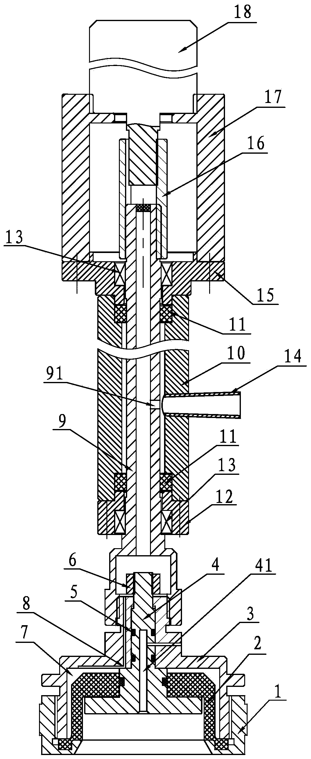
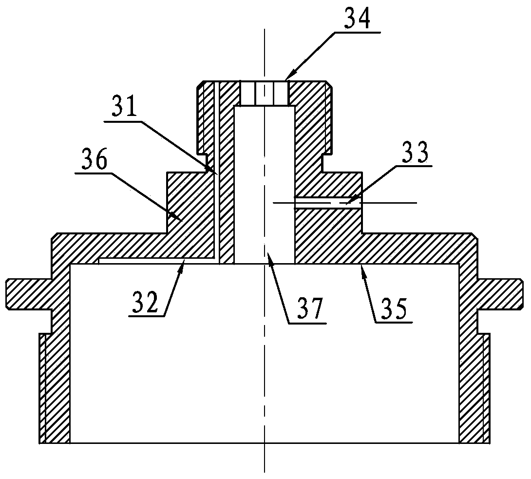
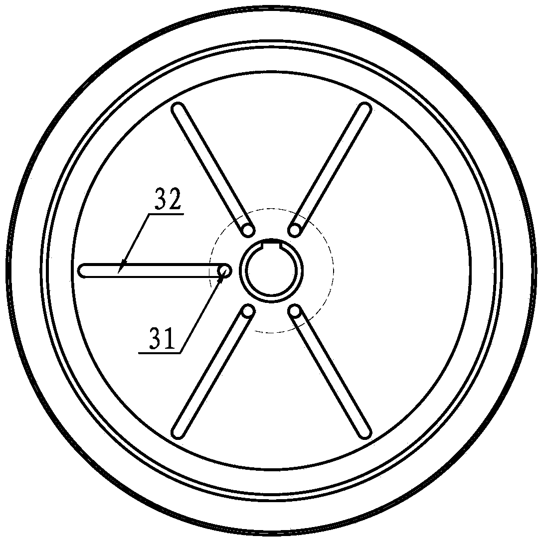
[0025] A pneumatic flexible clamping torque adjustable capping device, such as Figure 1 ~ Figure 3 As shown, it includes screw cap screw sleeve 1, elastic clamp ring 2, rotating cover seat 3, gland core 4, mandrel sealing ring 5, tightening nut 6, air cavity 7, air inlet 8, hollow rotating shaft 9 , sheath 10, axial sealing ring 11, lower bearing seat 12, bearing 13, air intake pipe 14, upper bearing seat 15, connection sleeve 16, connection seat 17 and air motor 18, and elastic clamp ring 2 is set in a sealed way through the seal On the gland core 4, the gland core 4 is tightly fitted in the matching hole 37 of the rotating cover base 3 through the mandrel sealing ring 5, and the torque transmission between the two is realized through the key in the circumferential direction, and the tightening nut 6 axially The limit is fixed, so that the...


PUM


Abstract

The invention discloses a pneumatic torque-adjustable cap screwing device capable of flexibly clamping, which comprises a cap screwing thread bushing, an elastic clamp ring, a rotary cover base, a gland core, a central spindle seal ring, a tightening nut, an air cavity, air inlet passages, a hollow rotating shaft, a protecting bush, an axial seal ring, a lower bearing pedestal, a bearing, an air inlet pipe, an upper bearing pedestal, an adapter sleeve, a connecting seat and a pneumatic motor, wherein the cap screwing thread bushing, the elastic clamp ring, the rotary cover base, the gland core, the central spindle seal ring, the tightening nut, the air cavity and the air inlet passages form a bottle cap pneumatic chuck; the hollow rotating shaft, the protecting bush, the axial seal ring, the lower bearing pedestal, the bearing, the air inlet pipe, the upper bearing pedestal, the adapter sleeve, the connecting seat and the pneumatic motor form a pneumatic cap screwing drive part; the bottle cap pneumatic chuck is utilized to flexibly clamp a bottle cap, the clamping force can be adjusted, the bottle cap cannot be damaged, and clamp marks cannot be preserved on the bottle cap. The pneumatic cap screwing drive part can stably screw the bottle cap in a fixed torque manner according to the predetermined requirements, and the torque of cap screwing can be adjusted and controlled. A pressure relief air passage communicated with the outside is arranged on the lower end surface of the gland core, so that a bottle cap can be conveyed to a certain position. The device has the advantages that the structure is simple, the pneumatic flexible clamp is realized, the pneumatic cap screwing is performed in a torque-adjustable manner, the cap screwing operation is stable and reliable, the cap screwing speed is high and steady, the running cost is low, and the maintenance is facilitated.

Description

Technical field: [0001] The invention relates to a bottle capping machine, in particular to a capping device on the capping machine. Background technique: [0002] The existing capping machines are equipped with a cap unscrambling machine and a cap feeder. The cap unscrambling machine straightens the caps and sends them to the bottle mouth through the cap feeder, and then the capping machine performs capping. The capping method has a belt type capping And fixed mechanical three-jaw swivel head. Although the belt screw cap can flexibly rotate the bottle cap without damaging the bottle cap, but with the elongation of the belt, the clamping force of the belt on the bottle cap is unstable and uncontrollable. If the screw is not tight or the screw is too tight, the bottle cap will be cracked, and the torque of the screw cap cannot be controlled. The fixed mechanical three-jaw rotating head is not only difficult to control the cap clamping force, but also the steel chuck will ca...

Claims


Application Information

Patent Timeline
Patent Type & Authority Applications(China)
IPC IPC(8): B67B3/20
Inventor 杨波袁兆军蒋文强司马铃尹奋中
Owner JIANGSU JINWANG PACKING SCI TECH CO LTD
Why Eureka
Try Eureka