
Driving device and driving method for wind turbine high-speed shaft

A technology for wind turbines and driving devices, which is applied to wind turbine components, wind turbines, wind turbine control, etc., can solve problems such as labor and insecurity, and achieve the effect of simple, efficient and flexible driving methods.

Inactive Publication Date: 2013-12-18
NANJING WIND POWER TECH
View PDF6 Cites 2 Cited by
  • Summary
  • Abstract
  • Description
  • Claims
  • Application Information

AI Technical Summary

Problems solved by technology

[0003] The previous method used manpower to use a long lever to pull the brake disc at the high-speed shaft end. Since the transmission ratio of the speed-up box between the high-speed end and the low-speed end is generally 100, the wind wheel only rotates 3.6 degrees for each revolution of the brake disc; On high-power wind turbines, this method is quite laborious and often requires two people to operate. It is difficult to quickly align the wind wheel lock with the positioning hole on the wind wheel in windy conditions, especially in the narrow space in the high-altitude cabin , once the high-speed shaft turns due to gusts of wind, an unsafe situation may arise

Method used


Image

  • Driving device and driving method for wind turbine high-speed shaft
  • Driving device and driving method for wind turbine high-speed shaft

Examples


Embodiment Construction

[0017] In order to make the above-mentioned purposes, features and advantages of the present invention more obvious and understandable, the specific implementation modes of the present invention will be described in detail below in conjunction with the accompanying drawings, so that the above-mentioned and other purposes, features and advantages of the present invention will be clearer. Like reference numerals designate like parts throughout the drawings. The drawings have not been drawn to scale, emphasis instead being placed upon illustrating the gist of the invention.

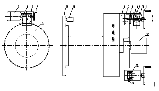
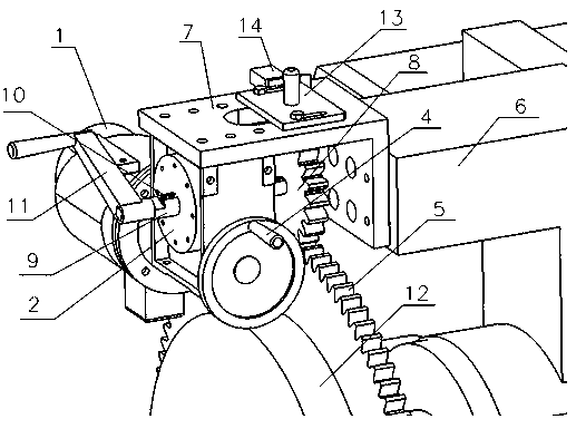
[0018] Combine below figure 1 and figure 2 The specific embodiment of the wind power generator high-speed shaft driving device of the present invention will be described in detail.

[0019] The wind power generator high-speed shaft driving device of the embodiment of the present invention includes a connecting plate 7, a reducer 2, a motor 1, an input shaft 3, an output shaft 9, a large hand wheel 11, a s...


PUM


Abstract

The invention provides a driving device for a wind turbine high-speed shaft. The driving device comprises a connecting board, a reducer, a motor, an input shaft, an output shaft, a large hand wheel, a small hand wheel, a removable key, a sliding small gear, a large gear and a trip switch. The motor can drive the high-speed shaft through the reducer, the small gear and the large gear. The invention further provides a driving method for the high-speed shaft, the circumferential direction of the high speed direction can be finely adjusted by rotating the small hand wheel. Furthermore, when electricity is out, the key in the output shaft can be removed, and the large hand wheel can be rotated to rotate the high-speed shaft. The driving device is simple and efficient, flexible to operate, and time saving and labor saving, and automatic locking of a wind wheel can be realized.

Description

technical field [0001] The invention relates to the technical field of wind power generation, in particular to a high-speed shaft drive device for a wind power generator and a driving method thereof. Background technique [0002] In the maintenance of wind turbines, it is necessary to rotate the high-speed shaft brake disc at the output shaft end of the speed-up gearbox, and drive the rotation of the wind wheel at the front low-speed shaft end through the speed-up box, thereby adjusting the relative position of the wind wheel and the wind wheel lock, so as to pass the wind Wheel lock to lock the wind wheel. [0003] The previous method used manpower to use a long lever to pull the brake disc at the high-speed shaft end. Since the transmission ratio of the speed-up box between the high-speed end and the low-speed end is generally 100, the wind wheel only rotates 3.6 degrees every time the brake disc rotates; On high-power wind turbines, this method is quite laborious and oft...

Claims


Application Information

Patent Timeline
Patent Type & Authority Applications(China)
IPC IPC(8): F03D11/02F03D7/00
CPCY02E10/72
Inventor 潘爱华王安正于长生赵宝德俞宗毅
Owner NANJING WIND POWER TECH
Learn More