Vacuum balance crankcase pressure device

A pressure device, crankcase technology, applied in the direction of brake transmission, transportation and packaging, piston pump, etc.

Active Publication Date: 2016-01-20
HANGZHOU BRANCH ZHEJIANG GEELY AUTOMOBILE RES INST +2
View PDF4 Cites 0 Cited by
  • Summary
  • Abstract
  • Description
  • Claims
  • Application Information

AI Technical Summary

Problems solved by technology

[0003] The purpose of the present invention is to overcome the shortcomings of the crankcase of the current engine that the extraction vacuum displacement is small and the pressure fluctuation is large during the working process, which affects the smooth operation of the engine, and to provide an engine with a large extraction vacuum displacement and small pressure fluctuation. Smooth crankcase pressure balanced vacuum extraction

Method used


Image

  • Vacuum balance crankcase pressure device

Examples


Embodiment Construction

[0011] The present invention will be further described below in conjunction with the accompanying drawings.

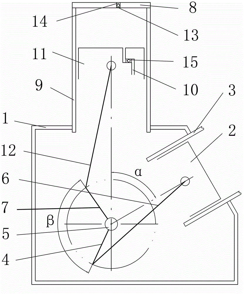
[0012] as attached figure 1 Shown: a vacuum balance crankcase pressure device, including a crankcase 1, a power cylinder 3 with a power piston 2 and connected to the crankcase 1, a power crank 4 and hinged with the crankcase 1 through a bearing The crankshaft 5 and the power connecting rod 6 hinged with the power crank 4 and the power piston 2 at both ends respectively through bearings, the vacuum crank 7 possessed by the crankshaft 5, and the vacuum cylinder block with a sealing plate 8 at one end and connected with the crankcase body 1 at the other end 9. The vacuum piston 11 with the inner through hole 10 passing through both ends and the vacuum connecting rod 12 hinged with the vacuum crank 7 and the vacuum piston 11 at both ends respectively through bearings; the sealing plate 8 has an outer through hole 13 through both ends and is fixed on the outer The outer on...


PUM


Abstract

The invention relates to the field of automobile engines and assisted braking and aims to provide an evacuating balance crankcase pressure device comprising a crankcase body, a power cylinder block, a crankshaft, a power link, a vacuum crank of the crankshaft, a vacuum cylinder block, a vacuum piston, and a vacuum link. The power cylinder block provided with a power piston is connected with the crankcase body. The crankshaft with a power crank is hinged to the crankcase body. Two ends of the power link are hinged to the power crank and the power piston respectively. One end of the vacuum cylinder block is provided with a seal plate, and the other end of the vacuum cylinder block is connected with the crankcase body. The vacuum piston is provided with an inner through hole passing two ends of the vacuum piston. Two ends of the vacuum link are hinged to the vacuum crank and the vacuum piston respectively. The seal plate is provided with an outer through hole passing two ends of the seal plate and an outer one-way valve fixed inside the outer through hole. An inner one-way valve with the intake end corresponding to the exhaust end of the outer one-way valve is disposed inside the inner through hole. The evacuating balance crankcase pressure device has the advantages that evacuation discharge is high, the pressure of the crankcase is low in fluctuation and the engine with the device operates stably.

Description

technical field [0001] The invention relates to the fields of automobile engines and brake boosters, in particular to a device for vacuuming and balancing crankcase pressure. Background technique [0002] In order to meet the increasingly stringent automobile energy-saving and environmental protection regulations, automobile engines are continuously miniaturized and supercharged, and three-cylinder and two-cylinder supercharged engines are gradually used. The invention of Chinese Patent Publication No. CN1923585A discloses an automobile brake booster auxiliary device, which consists of an intake manifold, a brake booster, a vacuum pipeline and a check valve. The direction valve is connected by a vacuum pipeline, and also includes a brake booster auxiliary pump and a connecting pipeline for increasing the vacuum degree. The automobile brake booster auxiliary device uses the intake manifold to extract vacuum for the brake booster of the whole vehicle. When the engine is a thr...

Claims


Application Information

Patent Timeline
Patent Type & Authority Patents(China)
IPC IPC(8): F04B37/14F04B35/01B60T13/52
Inventor 徐友朱小春刘岩沈源由毅冯擎峰
Owner HANGZHOU BRANCH ZHEJIANG GEELY AUTOMOBILE RES INST
Why Eureka
Try Eureka