Refraction and reflection light emitting device

A technology of catadioptric and light devices, which is applied in the field of catadioptric light emitting devices, can solve the problems of affecting the service life of LEDs, increasing the number of PCB boards, and the number of LEDs used, so as to improve the picture quality and reduce the number of LEDs used , the effect of increasing the irradiated area

Inactive Publication Date: 2013-12-18
SHINEON BEIJING TECH
View PDF11 Cites 5 Cited by
  • Summary
  • Abstract
  • Description
  • Claims
  • Application Information

AI Technical Summary

Problems solved by technology

[0003] The existing direct-lit backlight solutions have the following disadvantages: (1) Many LEDs are required. For example, for a 32-inch TV, at least 20 or 30 LEDs with medium power are required, and the cost is still high; (2) LED The number of LEDs used is too large, which leads to the increase of the number of LED strips used, that is, the number of PCB boards, which increases the cost; (3) the number of LEDs used is large, and in the same size space, the heat emitted is too much, which cannot be dissipated in time, which affects the performance of LEDs. service life

Method used


Image

  • Refraction and reflection light emitting device
  • Refraction and reflection light emitting device
  • Refraction and reflection light emitting device

Examples


example 1

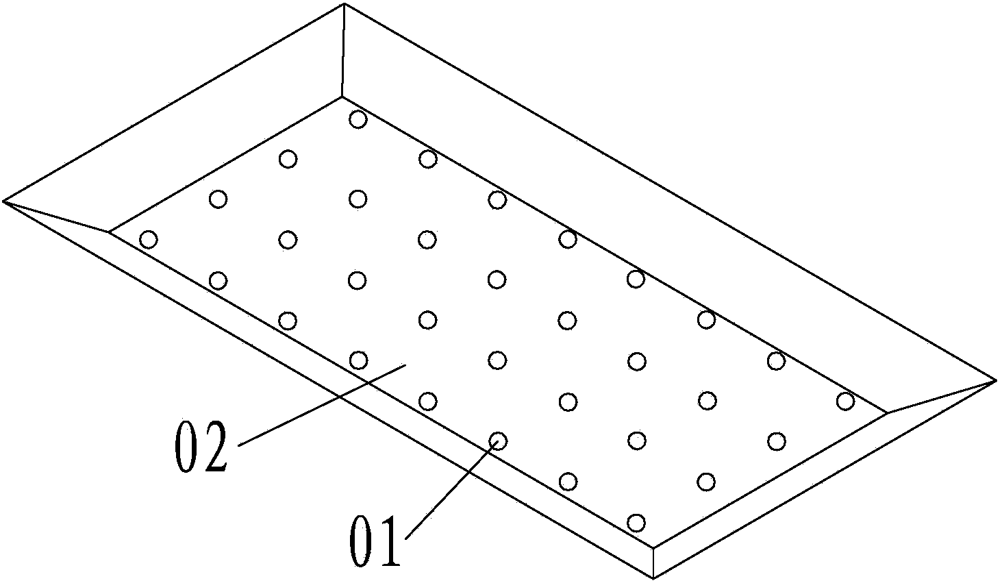
[0040] Example 1 Build a backlight module for a 32-inch backlight LCD TV

[0041] Such as Figure 4 As shown, using 10 LED light sources of 3W each, each LED light source cooperates with the large-angle catadioptric optical lens of the present invention, and the large-angle catadioptric optical lens divides the light emitted by the LED light source into three parts for processing respectively. The light emitted by the LED light source and its optical axis at an angle greater than 30° and not greater than 90° is refracted and incident on the diffuser plate, and the light emitted by the LED light source and its optical axis at an angle greater than 12° and not greater than 30° Through reflection and double refraction, the light facing the LED light source is formed. The light emitted by the LED light source and its optical axis within the range of an angle greater than 0° and not greater than 12° passes through reflection, refraction, and secondary reflection of the reflective s...

example 2

[0042] Example 2 Build a 10w panel light

[0043] Such as Figure 5 As shown, by using five 2W LED light sources, combined with the catadioptric optical lens and high reflectivity reflective sheet of the present invention, an efficient 10w panel light can be constructed.

[0044] Compared with the existing direct-type LED backlight module, the direct-type LED backlight module of the present invention has the following advantages:

[0045](1) The required number of LEDs can be reduced. For example, for 32-inch backlight products, the original 20-30 LEDs can be reduced to 10 or even less, thereby increasing the Pitch value and reducing the duty cycle. reduced costs;

[0046] (2) Due to the use of fewer LEDs, the consistency of LED light color can be better controlled and the picture quality of backlight products can be improved;

[0047] (3) Due to the use of high-reflectivity reflective sheets combined with catadioptric optical lenses for secondary reflection, the utilizatio...


PUM


Abstract

The invention discloses a refraction and reflection light emitting device. The divergence angle of an LED (light emitting diode) light beam is increased by a refraction and reflection optical lens with the special design, and therefore the radiation area of a single LED light source is enlarged. Furthermore, a reflector plate with the high reflectivity is cooperated with the refraction and reflection optical lens to finish big-angle optical diffusion, and the light energy use ratio is improved. Compared with the traditional bottom lighting type LED backlight module, the bottom lighting type LED backlight module applying the refraction and reflection light emitting device disclosed by the invention has the following advantages: (1) the number of the required LEDs can be reduced so as to increase a Pitch value, lower a duty ratio and lower the cost; (2) because few LEDs are used, the light color consistency of the LED can be better controlled, and the picture quality of the backlight product is improved; (3) the light energy use ratio and the backlight module luminance are improved; (4) the space occupied by the single LED is increased, thereby being favorable for heat loss, lowering the temperature of the backlight module, and prolonging the service life of the LED and the backlight module.

Description

technical field [0001] The invention relates to the fields of display and illumination, in particular to a catadioptric light emitting device. Background technique [0002] In recent years, the direct-lit type has gradually penetrated into the backlight field, and the fundamental driving force for it to replace the side-lit type is low cost. In the field of direct-lit backlights, existing technical solutions are realized by using large-angle optical lenses in combination with reflective sheets, diffusion plates, diffusion sheets and other film materials, such as figure 1 . However, the duty ratio H / P that can be achieved by this backlight solution is mostly 0.3 or higher (H refers to the distance between the PCB board and the diffuser plate, and P refers to the distance between the light source and the light source in the direct-down solution). [0003] The existing direct-lit backlight solutions have the following disadvantages: (1) Many LEDs are required. For example, fo...

Claims


Application Information

Patent Timeline
Patent Type & Authority Applications(China)
IPC IPC(8): F21V13/04F21Y101/02
Inventor 朱贺玲刘国旭
Owner SHINEON BEIJING TECH
Why Eureka
Try Eureka