Pipeline flaw detection system navigation and location method based on IMU (Inertial Measurement Unit)

An inertial measurement component, navigation and positioning technology, which is applied in directions such as navigation through speed/acceleration measurement, can solve the problems of being unable to meet the requirements of flaw detection and positioning, difficult to meet the use condition restrictions and positioning accuracy requirements, use condition restrictions, etc.

Inactive Publication Date: 2013-12-18
HARBIN ENG UNIV
View PDF1 Cites 14 Cited by
  • Summary
  • Abstract
  • Description
  • Claims
  • Application Information

AI Technical Summary

Problems solved by technology

[0003] For the flaw detection and positioning technology of oil and gas pipelines, the odometer / INS integrated navigation method is more common at present, but due to the large error of the odometer itself, the accuracy of the integrated navigation is low, which cannot meet the existing flaw detection and positioning of oil and gas pipelines. The commonly used system correction method is also not suitable for inertial navigation and positioning technology due to its limitations on system use conditions (low speed, equal latitude operation, etc.)
[0004] All in all, whether it is to use the integrated navigation system alone to locate the pipeline flaw detection, or to use the commonly used system correction technology to limit the system error, it is difficult to meet the requirements of the current oil and gas pipeline flaw detection technology for the limitation of use conditions and positioning accuracy

Method used


Image

  • Pipeline flaw detection system navigation and location method based on IMU (Inertial Measurement Unit)
  • Pipeline flaw detection system navigation and location method based on IMU (Inertial Measurement Unit)
  • Pipeline flaw detection system navigation and location method based on IMU (Inertial Measurement Unit)

Examples


Embodiment Construction

[0037] The present invention will be described in detail below in conjunction with specific embodiments.

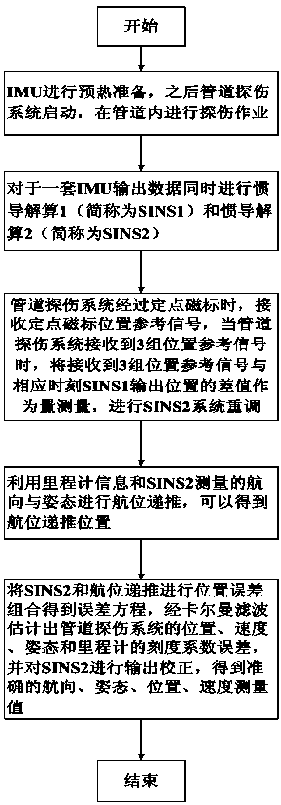
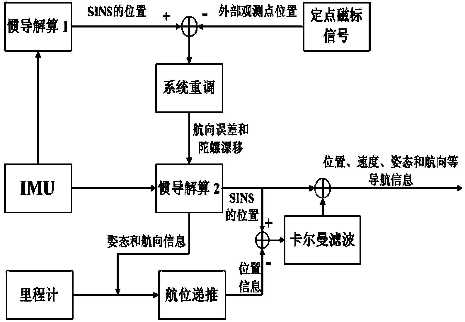
[0038] The pipeline flaw detection system is mainly composed of inertial measurement components and odometers. Among them, the inertial measurement component contains a gyroscope and an accelerometer for measuring inertial data, and an inertial navigation computer module for inertial navigation calculation, system readjustment and Kalman filtering; the odometer is installed on the vehicle of the inertial measurement component The tail of the vehicle moves close to the inner wall of the pipeline, so that the running distance and speed of the vehicle inside the pipeline can be obtained, and this information is transmitted to the inertial navigation computer module. In addition, a fixed-point magnetic mark base station is built every 1-2Km on the pipe wall. When the pipeline flaw detection system passes the current fixed-point magnetic mark, it can directly obtain the positi...


PUM


Abstract

The invention discloses a pipeline flaw detection system navigation and location method based on an IMU (Inertial Measurement Unit). The pipeline flaw detection navigation and location method comprises the following steps: carrying out two groups of inertial navigation calculation simultaneously on one set of IMU output data; when a pipeline flaw detection system passes through a fixed magnetic tag, receiving position reference signals of the fixed magnetic tag, when the pipeline flaw detection system receives three groups of position reference signals, readjusting an SINS2 (Strapdown Inertial Navigation System 2) by using a difference between three groups of received position reference signals and SINS1 output positions at corresponding moment as a measurement amount: measuring a course error delta K(tn+2) and a gyroscopic drift Epsilon and compensating, and correcting a position error of the SINS2; carrying out dead reckoning by using the speedometer information and a course and a gesture which are measured by the SINS2 to obtain a dead reckoning position; and carrying out position error combination on the SINS2 and the dead reckoning to obtain an error equation, estimating a position, a speed and a gesture of the pipeline flaw detection system and a calibration factor error of a speedometer through Kalman filtering, and carrying out output correction on the SINS2 to obtain accurate course, gesture, position and speed measurement values.

Description

technical field [0001] The invention relates to a navigation and positioning method for a pipeline flaw detection system based on an inertial measurement unit (IMU). The method has the advantages of high precision, less demand for external information, and does not limit the speed and latitude change of the pipeline flaw detection system. It is of great significance to improve the precision of oil pipeline flaw detection system. Background technique [0002] In the process of oil pipeline technology development, the Strapdown Inertial Navigation System (SINS) can continuously and real-time provide position, velocity and attitude information due to its fully automatic navigation characteristics, as well as high short-term accuracy. Due to the advantages of limited weather conditions, it has become the core part of the pipeline flaw detection system. It mainly uses the real-time measurement information obtained by the inertial measurement unit (IMU) to solve the navigation and...

Claims


Application Information

Patent Timeline
Patent Type & Authority Applications(China)
IPC IPC(8): G01C21/16
Inventor 奔粤阳杨娇龙李敬春车延庭刘新源赵维珩阮双双杨祥龙谢松霖林星辰
Owner HARBIN ENG UNIV
Why Eureka
Try Eureka