
Method for improving spectral resolution of soft X-ray flat focal field spectrometer

A spectral resolution, X-ray technology, applied in radiation pyrometry, spectrometry/spectrophotometry/monochromator, instruments, etc., can solve the problems of system complexity, difficulty in miniaturization, loss of luminous flux, etc. , to achieve the effect of improving spectral resolution

Active Publication Date: 2015-04-08
UNIV OF SCI & TECH OF CHINA
View PDF1 Cites 0 Cited by
  • Summary
  • Abstract
  • Description
  • Claims
  • Application Information

AI Technical Summary

Problems solved by technology

However, there are some corresponding problems in these methods: reducing the slit width to improve the spectral resolution may cause a serious loss of light flux; increasing the spectral imaging distance has two problems. First, the structure of the spectrometer becomes larger and it is difficult to To achieve miniaturization, second, for the same spectral range, the width of the spectral image plane becomes larger, and when the width of the plane detector is not enough to receive the entire image plane, it is necessary to move the plane detector in the width direction to receive data multiple times to obtain the entire spectrum Like, doing so complicates the system and doesn't allow for real-time

Method used


Image

  • Method for improving spectral resolution of soft X-ray flat focal field spectrometer
  • Method for improving spectral resolution of soft X-ray flat focal field spectrometer
  • Method for improving spectral resolution of soft X-ray flat focal field spectrometer

Examples


Embodiment 1

[0038] Select the grating in the literature (Performance of laminar-type holographic grating for a soft x-ray flat-field spectrograph in the0.7-6nm region) for partition design, the center line density of the grating is 2400gs / mm, and the line density parameter is b 2 =-62,b 3 =40007.5, b 4 =-369802.6, the radius of curvature of the base is 15920mm, and the wavelength used is 0.7-6nm.

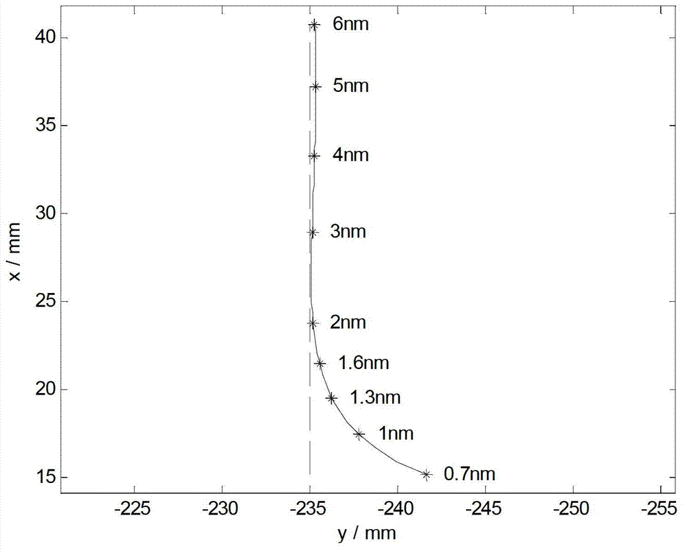
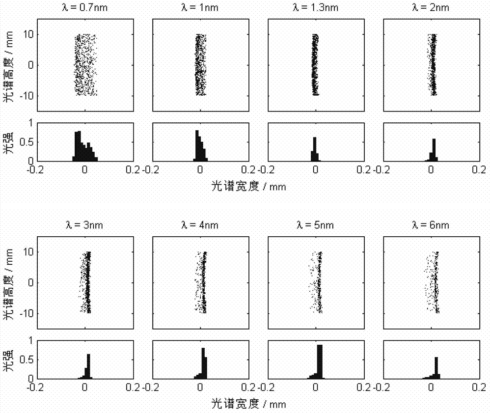
[0039] according to figure 2 with image 3 According to the analysis, the aberration in the 0.7-1.3nm band is serious, so this band is selected for further optimization. First, if Figure 4 Divide the grating into regions I, II and III, and investigate the imaging characteristics of different grating regions at each wavelength ( Figure 5 ), it can be seen that the aberrations in areas I and II are relatively large, and the image centers of the three areas are not at the same height, which leads to serious aberrations in this band. According to the previous analysis, in order to further ...

Embodiment 2

[0041] The grating is the same as Example 1, and the designed partition groove parameters: the duty ratios corresponding to regions I, II and III are 0.1, 0.2 and 0.425 respectively, and the groove depths are 15, 15 and 4.5nm respectively. The ray tracing results in Image 6 , 7 In , 8, at 0.8nm, the spectral resolution does not change much compared to Example 1, from 383 to 425, at 1.1nm, it increases from 620 to 712, and at 4.0nm, the spectral resolution changes from 1035 to 1169 . Compared with Example 1, Example 2 further suppresses the diffraction efficiency in the larger aberration region, and improves the spectral resolution to a certain extent.


PUM


Abstract

The invention provides a method for improving spectral resolution of a soft X-ray flat focal field spectrometer. A method that optical gratings are used for partitioning is adopted, on the premise that the structure of the spectrometer is not changed, trough type parameters of various partitions are respectively designed, diffraction efficiency of each partition is changed, and thus aberrations are further corrected to improve the spectral resolution. The method has the advantages that in the manufacturing of the optical gratings, partitioning is carried out in the direction vertical to stripes, different trough type parameters are respectively designed, distribution of the diffraction efficiency of each partition is changed, and the aberrations are further corrected; on the premise of guaranteeing the diffraction efficiency, proper partition structure trough type parameters are selected, resolution of wave lengths with serious aberrations is improved, resolution of other wave lengths is not influenced, and thus the spectrometer obtains good resolution on the whole use wave band.

Description

technical field [0001] The invention relates to a flat-focus field spectrometer working in the soft X-ray band, which is used for X-ray plasma diagnosis, and in particular to a method for improving the spectral resolution of a soft X-ray flat-focus field spectrometer, which utilizes grating partition technology without changing the spectrometer structure parameter to increase the spectral resolution of the spectrometer. Background technique [0002] Prior art 1 (Performance of laminar-type holographic grating for a soft x-ray flat-field spectrograph in the0.7-6nm region) the structure of the flat-field spectrograph is as follows figure 1 As shown, the concave grating used not only has the dispersion function but also has imaging characteristics, and does not require other imaging components, so the spectrometer can be miniaturized. The system images the spectrum in a plane. Compared with the Rowland circle imaging system (imaging on a circle), it can be easily coupled with ...

Claims


Application Information

Patent Timeline
Patent Type & Authority Patents(China)
IPC IPC(8): G01J3/28G01J3/02
Inventor 刘正坤陈火耀王庆博刘颖付绍军
Owner UNIV OF SCI & TECH OF CHINA
Learn More