Electrical axis optical calibration system of spaceborne microwave tracking-pointing radar and calibration method thereof

A calibration method, satellite-borne microwave technology, applied to radio wave measurement systems, instruments, etc., can solve problems such as inconvenient installation of cube mirrors, difficulty in ensuring installation accuracy, and complicated measurement work, so as to facilitate repeated measurements, improve calibration accuracy, The effect of ensuring high precision and high reliability

Inactive Publication Date: 2013-12-18
SHANGHAI RADIO EQUIP RES INST
View PDF3 Cites 48 Cited by
  • Summary
  • Abstract
  • Description
  • Claims
  • Application Information

AI Technical Summary

Problems solved by technology

In order to obtain higher calibration accuracy, it is necessary to move the transponder repeatedly, which requires a lot of complicated measurement work
In addition, for non-cooperative and autonomous radars, the target simulator is usually used to simulate the target echo signal. It is not convenient to install the cube mirror on the target simulator (usually a horn antenna), and even if it is installed, it is difficult to ensure the installation accuracy.
Therefore, the calibration method given in this document cannot be effectively used for electrical axis calibration of spaceborne microwave tracking and pointing radar

Method used


Image

  • Electrical axis optical calibration system of spaceborne microwave tracking-pointing radar and calibration method thereof
  • Electrical axis optical calibration system of spaceborne microwave tracking-pointing radar and calibration method thereof
  • Electrical axis optical calibration system of spaceborne microwave tracking-pointing radar and calibration method thereof

Examples


Embodiment Construction

[0074] The present invention will be further elaborated below by describing a preferred specific embodiment in detail in conjunction with the accompanying drawings.

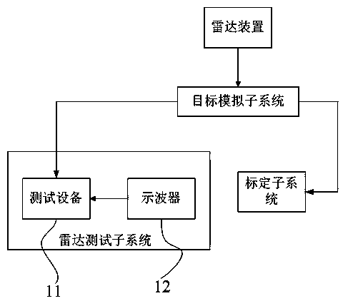
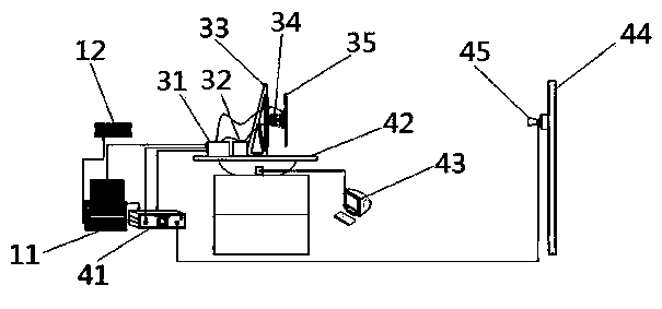
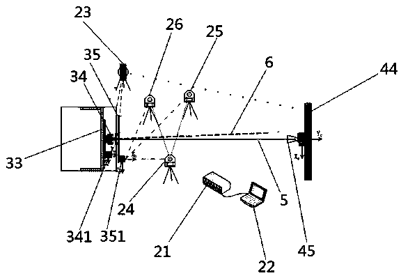
[0075] Such as figure 1 and figure 2 As shown, an electrical axis optical calibration system for a spaceborne microwave tracking and pointing radar includes a radar test subsystem, a calibration subsystem, a radar device, and a target simulation subsystem; the target simulation subsystem includes a target simulation source 41, and a two-dimensional test turntable 42. The two-dimensional test turntable controller 43 connected to the two-dimensional test turntable 42, the two-dimensional scanning frame 44 and the horn antenna 45 arranged on the two-dimensional scanning frame 44; the radar test subsystem includes the test equipment 11 and the oscilloscope 12 The oscilloscope 12 is connected with the test equipment 11; the radar device, the eye model horn antenna 45 and the test equipment 11 are connected with the ...


PUM


Abstract

The invention discloses an electrical axis optical calibration system of a spaceborne microwave tracking-pointing radar and a calibration method of the electrical axis optical calibration system. The electrical axis optical calibration system comprises a radar testing subsystem, a calibration subsystem, a radar device and a target simulation subsystem. The target simulation subsystem comprises a target simulation source, a two-dimensional testing rotary table, a two-dimensional testing rotary table controller connected with the two-dimensional testing rotary table, a two-dimensional scanning frame and a target simulation horn antenna arranged on the two-dimensional scanning frame. The calibration method comprises the first step of calibrating the mounting precision of a radar antenna and a driving mechanism, the second step of calibrating the consistency of a radar electric axis and a radar antenna mechanical axis and the third step of correcting the radar according to a calibration result. According to the electrical axis optical calibration system of the spaceborne microwave tracking-pointing radar and the calibration method, high-precision calibration can be carried out on the radar in a compact field, the requirement of the radar for the temperature, the humidity and the cleanliness of used environment is met, the non-contact calibration of the spaceborne microwave tracking-pointing radar is achieved, the used measuring instruments are small in number and high in precision, the calculation of data can be automatically completed, and the high precision and the high reliability of the radar are guaranteed.

Description

technical field [0001] The invention relates to the technical field of testing and testing of payloads in aerospace space, and in particular to an electric axis optical calibration system and a calibration method of a spaceborne microwave tracking and pointing radar. Background technique [0002] In the prior art, the spaceborne radar mainly ensures the consistency of the target information obtained in the radar measurement coordinate system and the spacecraft body coordinate system through the cubic mirror installed on the radar and the spacecraft body. Therefore, the accurate calibration of the rotation relationship between the radar measurement coordinate system and the cube mirror coordinate system can ensure that the spaceborne radar provides accurate and reliable target information to the spacecraft. To achieve this purpose, the installation accuracy of the radar antenna and the drive mechanism, and the consistency between the radar electrical axis and the antenna mech...

Claims


Application Information

Patent Timeline
Patent Type & Authority Applications(China)
IPC IPC(8): G01S7/40
Inventor 江利中吉峰李雁斌黄勇邹波
Owner SHANGHAI RADIO EQUIP RES INST
Why Eureka
Try Eureka