Finite element analysis method of composite material

An analysis method and technology of composite materials, applied in the field of finite element analysis of composite materials, can solve the problems of difficult accurate analysis and calculation of composite materials, non-uniform winding directions of composite materials, etc.

Inactive Publication Date: 2013-12-18
XIANGTAN ELECTRIC MFG CORP LTD
View PDF5 Cites 18 Cited by
  • Summary
  • Abstract
  • Description
  • Claims
  • Application Information

AI Technical Summary

Problems solved by technology

[0002] At present, when calculating the mechanical properties of composite materials, traditional mathematical formulas are often used for calculation. For composite materials that are wound and formed, the winding direction of the composite material is not uniform and there is a certain pre-tightening force. After winding, it needs to

Method used


Image

  • Finite element analysis method of composite material
  • Finite element analysis method of composite material
  • Finite element analysis method of composite material

Examples


Embodiment Construction

[0013] The present invention will be further described below in conjunction with drawings and embodiments.

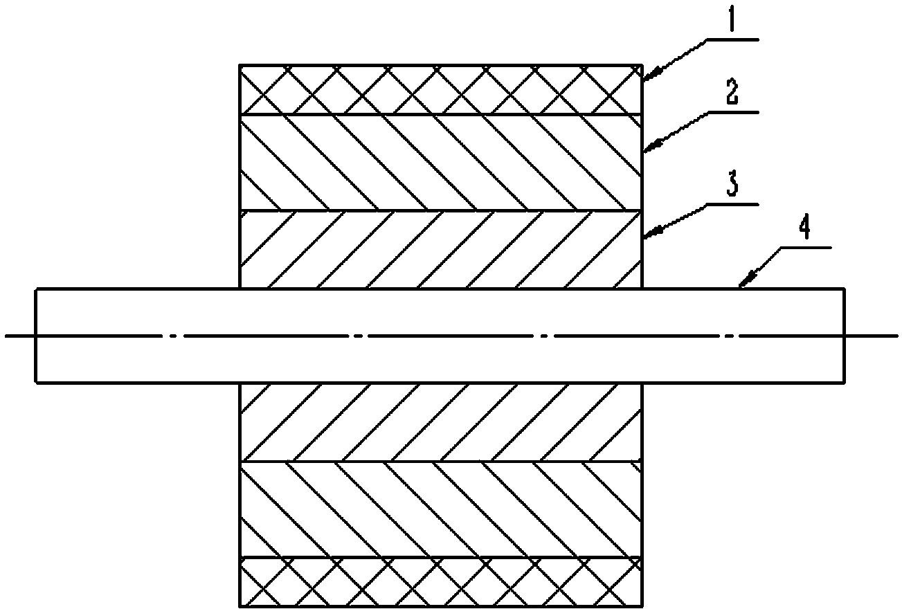
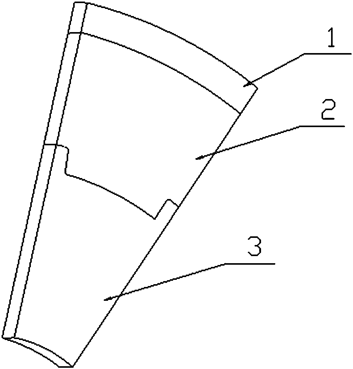
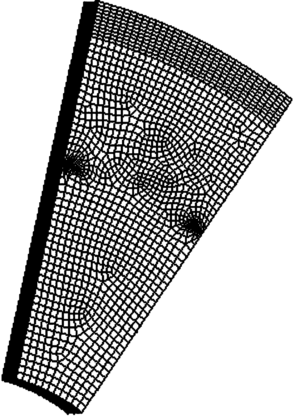
[0014] Refer to attached figure 1 , is a motor rotor structure, which includes a protective cover 1, a magnetic steel 2, a rotor core 3, and a rotating shaft 4. The protective cover 1 is a composite material with a total thickness of 2mm, the first to fourth layers are fiber A, the winding direction is at an angle of 30 degrees to the rotating shaft 4, the thickness of the first to fourth layers is 0.1mm, and the pre-tightening force of each layer is 500N , the fifth to twelfth layers are fiber B, the winding direction is at an angle of 45 degrees to the rotating shaft 4, the thickness is 0.2mm, and the preload force of each layer is 600N. When the motor is running, the protective cover 1 will be subjected to the centrifugal force of the magnetic steel 2 . The entire finite element analysis simulates and analyzes the stress situation of the protective cover 1 during t...


PUM


Abstract

The invention relates to a finite element analysis method of a composite material. The method comprises the following steps: 1, building a mathematic model, i.e. building a three-dimensional model by utilizing three-dimensional software; 2, defining material attributes for the built model by utilizing finite element software, performing mesh generation, and converting the model into a finite element model, wherein the material attributes are defined according to the anisotropy of the material, i.e. the winding direction and winding thickness of each layer and the failure criterion of the material are defined; 3, loading boundary conditions on the finite element model, loading conditions on the model according to an actual stress situation, and simulating the actual situation; 4, performing finite element analysis, so as to obtain a stress distribution cloud picture and a displacement situation graph. When the finite element analysis method is used for analysis, the material attributes are defined according to the anisotropy of the material, and calculation is performed respectively according to the winding direction and winding thickness of each layer, so that the winding direction and residual pretightening force of each layer of the composite material can be well simulated.

Description

technical field [0001] The invention relates to a finite element analysis method of a composite material. Background technique [0002] At present, when calculating the mechanical properties of composite materials, traditional mathematical formulas are often used for calculation. For composite materials that are wound and formed, the winding direction of the composite material is not uniform and there is a certain pre-tightening force. After winding, it needs to be cured at high temperature. During the curing process, the pre-tightening force of each layer of fibers is released to varying degrees. The traditional mathematical formula method is difficult for composite materials with different winding directions and different residual pre-tightening forces for each layer. Perform accurate analysis and calculations. Contents of the invention [0003] The object of the present invention is to overcome the above defects and provide an accurate finite element analysis method fo...

Claims


Application Information

Patent Timeline
IPC IPC(8): G06F17/50
Inventor 程秀杰张越雷陈雷曾湘黔万翔
Owner XIANGTAN ELECTRIC MFG CORP LTD
Why Eureka
Try Eureka