Method for processing LED (Light-Emitting Diode) variable message sign

A processing method and marking technology, which is applied in the processing field of LED variable information signs, can solve problems such as poor uniformity, uneven LED brightness, uneven lens height, etc., and achieve the effect of solving sealing problems

Active Publication Date: 2013-12-18
YAHAM OPTOELECTRONICS CO LTD
View PDF7 Cites 2 Cited by
  • Summary
  • Abstract
  • Description
  • Claims
  • Application Information

AI Technical Summary

Problems solved by technology

[0004] Poor uniformity: due to the inability to guarantee the matching depth of the lens and the metal panel when inser

Method used


Image

  • Method for processing LED (Light-Emitting Diode) variable message sign
  • Method for processing LED (Light-Emitting Diode) variable message sign
  • Method for processing LED (Light-Emitting Diode) variable message sign

Examples


Embodiment Construction

[0029] The present invention will be further described below in conjunction with the accompanying drawings.

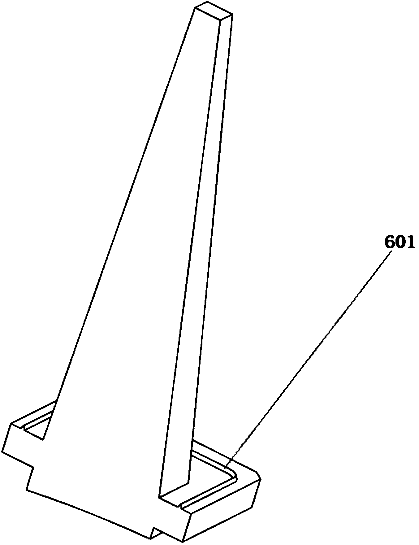
[0030] Step 1: Add ultrasonic lines to the mounting surface of the lens.

[0031] The section of the ultrasonic wire needs to be designed as an isosceles triangle. See picture. Welding is uniform, starting from the tip of the isosceles triangle, the amount of glue at both ends of the isosceles triangle is equal, the flatness after welding can be guaranteed, and the uniformity and upright consistency of the lens after welding to the lens holder is guaranteed.

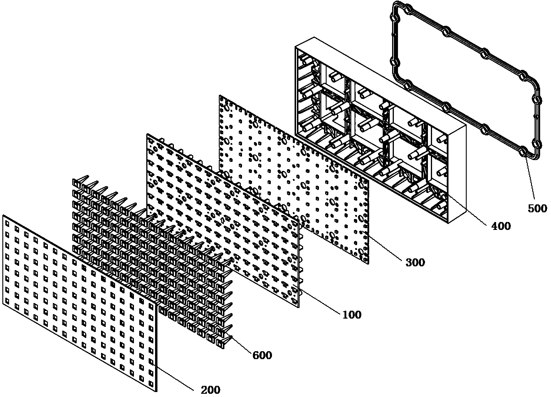
[0032] Step 2: Design and produce the metal fixed base mold for ultrasonic welding for the lens holder.

[0033] The shape of the bottom mold adopts a hollow close fit design, so that the lens holder and the lens can be embedded in the bottom mold more closely. The contact distance between the lens holder and the bottom mold should be kept between 0.05mm and 0.08mm. If it exceeds, it will affect the uniformity...


PUM


Abstract

The invention provides a method for processing an LED (Light-Emitting Diode) variable message sign. The method comprises the following steps: step 1, increasing ultrasonic lines for a mounting surface of lenses; step 2, designing and producing a metal fixing bottom die for ultrasonic welding for a lens support; step 3, selecting a lens support material and a lens material easy for ultrasonic welding fusion; step 4, fixing the lens support onto the metal fixing bottom die; step 5, tidily placing the lenses on the lens support, and ensuring that each lens is fixed by both a positioning column of the lens and a positioning hole of a bracket; step 6, adjusting an ultrasonic machine for welding. As the ultrasonic welding realizes the fusion of two similar materials, the sealing problem is thoroughly solved, and the best surface waterproof effect at present is achieved. Through the isosceles triangular section design of the ultrasonic lines and a precise bottom die design, the ultrasonic welding can cause the uniform match of the lens support and the lenses to achieve the best effect at present.

Description

technical field [0001] The invention relates to an assembly method, in particular to a processing method of an LED variable information sign. Background technique [0002] In the prior art, the LED variable information sign adopts a front panel made of sheet metal technology to cooperate with a lens, and then uses a sheet metal front panel on which a lens is installed to cooperate with an LED light board and a bottom shell assembly. [0003] The above-mentioned structure has poor airtightness: because the aperture and flatness of the metal panel are not completely uniform, there is a gap in the contact between the lens and the metal panel, which causes water leakage. [0004] Poor uniformity: Since the matching depth of the lens and the metal panel cannot be guaranteed when inserted, the height of the lens is different, resulting in uneven brightness of the LED light after passing through the lens. Contents of the invention [0005] In order to solve the problems in the p...

Claims


Application Information

Patent Timeline
IPC IPC(8): G09F9/33F21V5/04F21V31/00
Inventor 焦伟棋周双军周旭王占明
Owner YAHAM OPTOELECTRONICS CO LTD
Why Eureka
Try Eureka