
Cooling control method, cooling control device and cooling system of energy storage power supply

An energy storage power supply and cooling control technology, which is applied in the field of cooling systems and cooling control devices, can solve the problems affecting the service life of the energy storage power supply and prolong the time for the temperature of the energy storage power supply to return to the normal temperature range, so as to reduce time, Improve the service life and avoid the effect of rapid rise

Active Publication Date: 2013-12-18
ZHUZHOU ELECTRIC LOCOMOTIVE CO
View PDF4 Cites 10 Cited by
  • Summary
  • Abstract
  • Description
  • Claims
  • Application Information

AI Technical Summary

Problems solved by technology

[0005] Although the cooling system of the energy storage power supply controls the temperature to a certain extent, because the cooling system is passively controlled, that is, the cooling fan will only be turned on when the temperature inside the energy storage power supply has risen to the upper threshold, which will prolong the use of the power supply. The time it takes for the internal temperature of the energy storage power supply to return to the normal temperature range makes the energy storage power supply in a high temperature environment for a long time, which affects the service life of the energy storage power supply

Method used


Image

  • Cooling control method, cooling control device and cooling system of energy storage power supply
  • Cooling control method, cooling control device and cooling system of energy storage power supply

Examples


Embodiment Construction

[0046] One of the purposes of the present invention is to provide a cooling control method for the energy storage power supply, so as to shorten the time for the internal temperature of the energy storage power supply to return to the normal temperature range, to reduce the time for the energy storage power supply to be in a high temperature environment, and to improve the temperature of the energy storage power supply. service life of the power supply;

[0047]Another object of the present invention is to provide a cooling control device that can realize the above cooling control method for energy storage power supply;

[0048] Another object of the present invention is to provide a cooling system comprising a cooling air channel inside the energy storage power supply, a fan, and the above-mentioned cooling control device.

[0049] In order to enable those skilled in the art to better understand the solutions of the present invention, the present invention will be further des...


PUM


Abstract

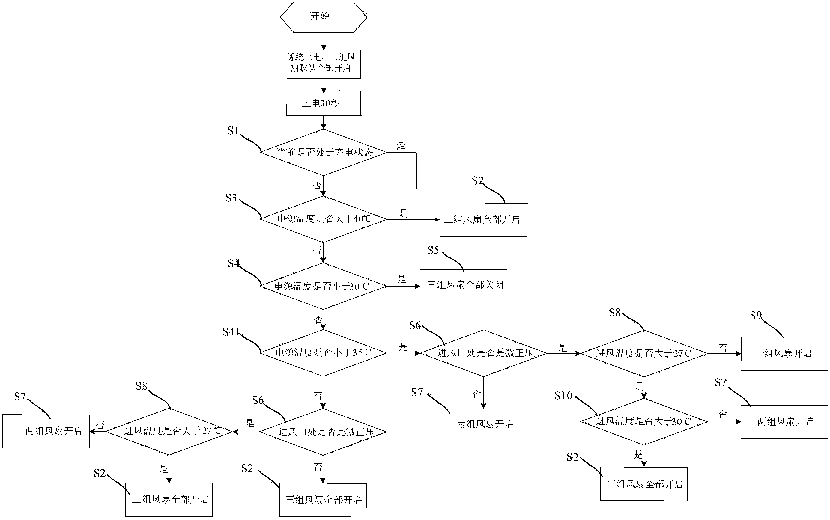
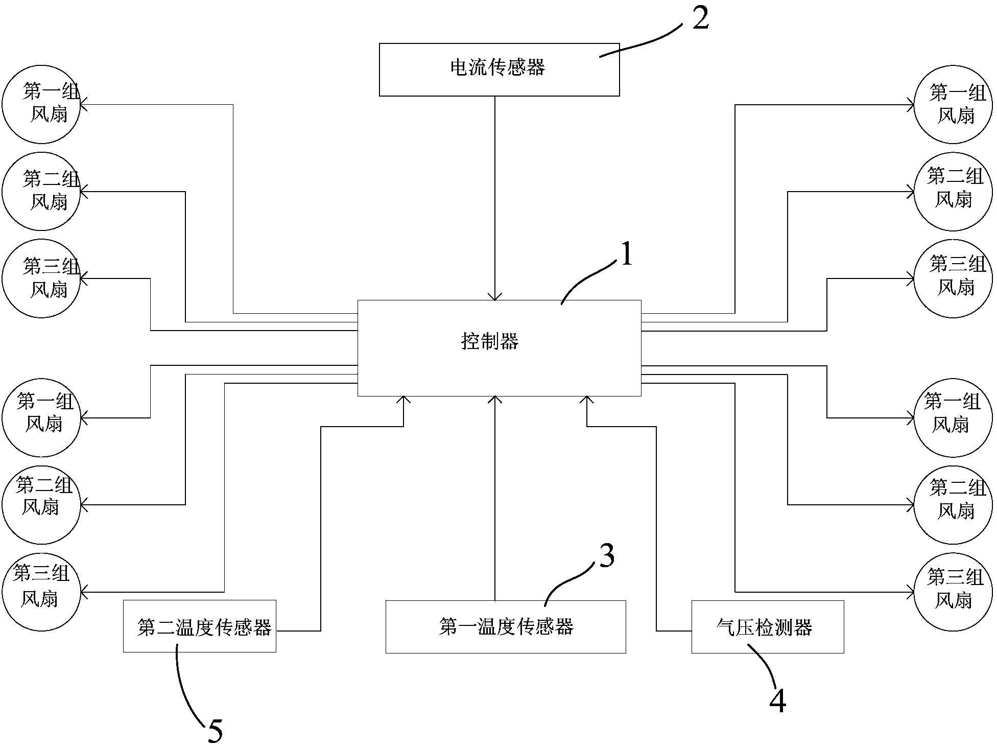
The invention discloses a cooling control method of an energy storage power supply. The energy storage power supply is provided with a plurality of groups of fans, wherein each group of fans comprises a plurality of fans positioned at different parts. The cooling control method comprises the following steps: (1) detecting whether the energy storage power supply is in a charging state and entering the step (2) if yes; and (2) controlling first preset groups of fans to start. The cooling control method disclosed by the invention is capable of performing active cooling and radiating through analysis of temperature influence factors of the energy storage power supply and starting to cool the energy storage power supply when the temperature of the energy storage power supply is not raised, so that the rapid rise of the temperature in the energy storage power supply can be effectively avoided; meanwhile, the time of the energy storage power supply in a high-temperature environment can be effectively shortened and the service life of the energy storage power supply can be prolonged. The invention also discloses a cooling control device of the energy storage power supply capable of realizing the cooling control method and a cooling system of the energy storage power supply; the cooling system comprises the cooling control device, the fans and air cooling channels of the energy storage power supply.

Description

technical field [0001] The invention relates to the technical field of rail transit vehicles, in particular to a cooling control method, a cooling control device and a cooling system for an energy storage power supply of a rail transit vehicle. Background technique [0002] Energy storage power supply is mainly used in energy storage rail transit vehicles. The so-called energy storage rail transit vehicles refer to modern trams that use supercapacitors to store electric energy, and use the passengers to get on and off the platform within tens of seconds to quickly complete Charging, one charge can ensure that the energy storage rail vehicle runs to the next station before charging. [0003] This is the first time that all supercapacitors are used as the sole power supply of modern trams. The power supply composed of supercapacitors realizes fast charging and discharging. Due to the short charging time, there will be a large charging current (600A-900A) during the charging pr...

Claims


Application Information

Patent Timeline
IPC IPC(8): H01M10/50B60K11/06F04D27/00
CPCY02E60/10
Inventor 张伟先张彦林陈中杰邓谊伯汪俊胡润文黄钰强王乐沈朝喜文午柯建明王雪莲
Owner ZHUZHOU ELECTRIC LOCOMOTIVE CO
Learn More