Forced air cooling method and device for isolated-phase enclosed busbar

A technology of closed busbar and air cooling device, applied in the direction of cooling busbar device, etc., can solve the problems of poor cooling effect and complex structure, and achieve the effects of excellent cooling effect, high heat exchange efficiency and simple equipment

Inactive Publication Date: 2013-12-18
BEIJING POWER EQUIP GRP +1
View PDF5 Cites 5 Cited by
  • Summary
  • Abstract
  • Description
  • Claims
  • Application Information

AI Technical Summary

Problems solved by technology

[0013] The purpose of the present invention is to provide a method and device for forced air cooling of an isolated phase-enclosed busbar, so as to solve the problems existing in the prior art such as complicated structure or poor cooling effect.

Method used


Image

  • Forced air cooling method and device for isolated-phase enclosed busbar
  • Forced air cooling method and device for isolated-phase enclosed busbar
  • Forced air cooling method and device for isolated-phase enclosed busbar

Examples


Embodiment Construction

[0027] The present invention will be described in further detail below in conjunction with the accompanying drawings and specific embodiments.

[0028] In order to solve the problems existing in the current single-air system and double-air system used for cooling isolated-phase closed busbars, the present invention provides a method and device for forced-air cooling of separated-phase closed busbars with the characteristics of mixed air.

[0029] Since the method and the device of the present invention have the same technical concept, in order not to create redundant descriptions, only the device embodiment of the present invention will be specifically described below. Those skilled in the art should understand that, according to the device embodiment of the present invention, they can reasonably infer various implementation manners of the method provided by the present invention.

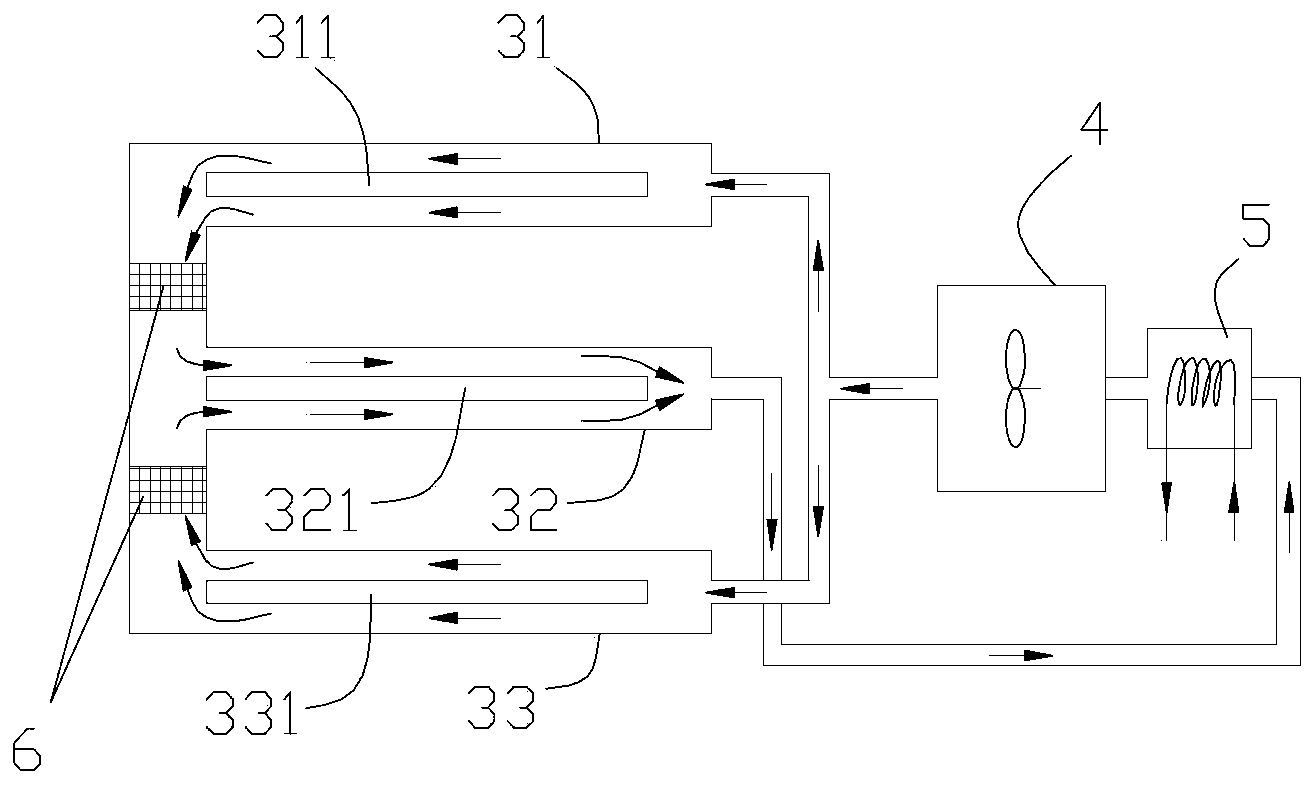
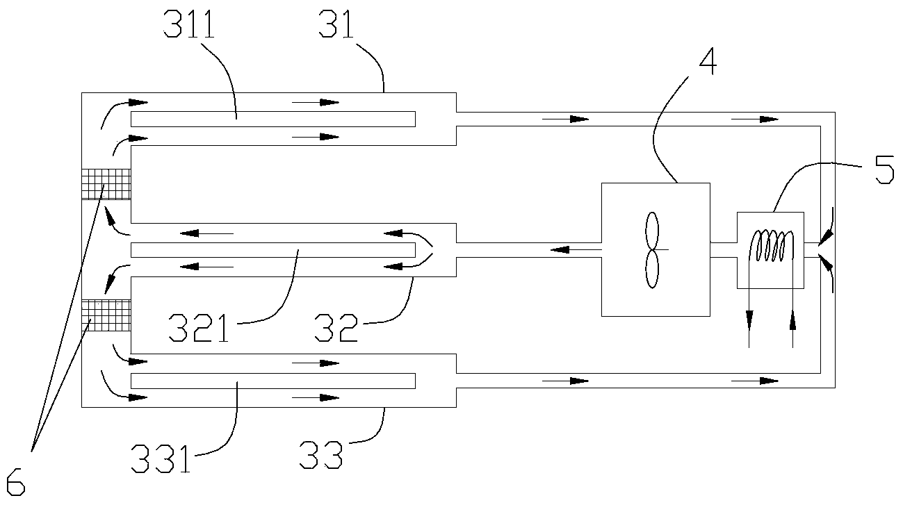
[0030] Such as Figure 6 As shown, the device embodiment of the present invention shown includ...


PUM


Abstract

The invention provides a forced air cooling method and device for an isolated-phase enclosed busbar. The forced air cooling method is used for cooling an air cooling busbar with a shell and a tubular conductor and includes the following steps that cold air flows in the same direction as an interlayer between the shell and the conductor along the interior of the conductor of the air cooling busbar. The forced air cooling device comprises a circulation fan, an air cooler and the air cooling busbar used for cooling the shell and the tubular conductor and further comprises an input channel and the interlayer, wherein the input channel is used for being connected between an air outlet of the circulation fan and the first end of the air cooling busbar, and the interlayer is used for conveying the cold air output by the circulation fan into the conductor of the air cooling busbar and into the portion between the shell and the conductor. According to the air cooling method and device, the inner surface and the outer surface of the busbar conductor can make direct contact with air flow, equipment layout is simple, the cooling effect is more excellent, the heat exchange efficiency is high, the problem of insulation of an air inlet and the air outlet is solved, and the problem of isolation of the interlayer and an inner tube of the conductor in a double-air system does not need to be considered too much.

Description

technical field [0001] The present invention relates to the technical field of forced air-cooled isolated-phase closed busbar (other parts or simply called air-cooled busbar), in particular to a forced-air-cooled method and device for separated-phase enclosed busbar. Background technique [0002] The isolated-phase closed busbar is a large current transmission device widely used in the lead-out circuit of 50MW and above generators and the branch circuit of the plant. Such as figure 1 As shown, the A-phase 21, B-phase 22, and C-phase 23 of the isolated-phase closed bus are mainly used between the outlet of the generator 13 located in the indoor 11 and the main transformer 14 located in the outdoor 12, and are used to transmit the power generated by the generator 13. electrical energy. Such as Figure 2-Figure 5 As shown, the phase-isolated closed busbar is mainly composed of conductors 311 / 321 / 331, housings 31 / 32 / 33 or conductors 811 / 821 / 831, housings 81 / 82 / 83 and insulati...

Claims


Application Information

Patent Timeline
Patent Type & Authority Applications(China)
IPC IPC(8): H02G5/10
Inventor 张烈靳智鹏肖磊金立东赵悦胡婷婷张微陈潮袁野
Owner BEIJING POWER EQUIP GRP
Why Eureka
Try Eureka