Variable-speed hub motor

A variable speed hub and motor shaft technology, applied in the field of wheels, can solve the problems of easy deformation of the support shaft, threat to driving safety, and lack of heat dissipation, so as to achieve the effects of not easy to break and deform, simple and direct adjustment, and improve power performance

Inactive Publication Date: 2013-12-18
蔡旭阳
View PDF0 Cites 6 Cited by
  • Summary
  • Abstract
  • Description
  • Claims
  • Application Information

AI Technical Summary

Problems solved by technology

The hollow support shaft of the wheel hub of this structure increases the difficulty of processing and greatly weakens the rigidity and strength of the support shaft due to the adjustment rod hole, guide groove and power cord hole. pose a threat to driving safety
In addition, because the motor is wrapped by the hub ring, the heat emitted by the motor during operation cannot be effectively dissipated, and the motor and components are easily burned due to overheating.

Method used


Image

  • Variable-speed hub motor
  • Variable-speed hub motor
  • Variable-speed hub motor

Examples


Embodiment 1

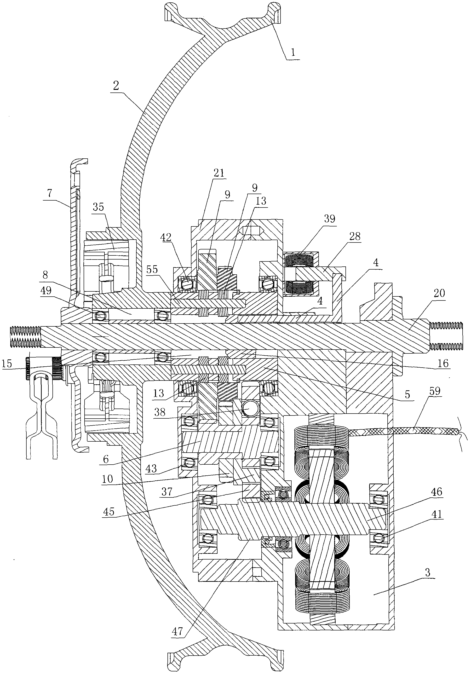
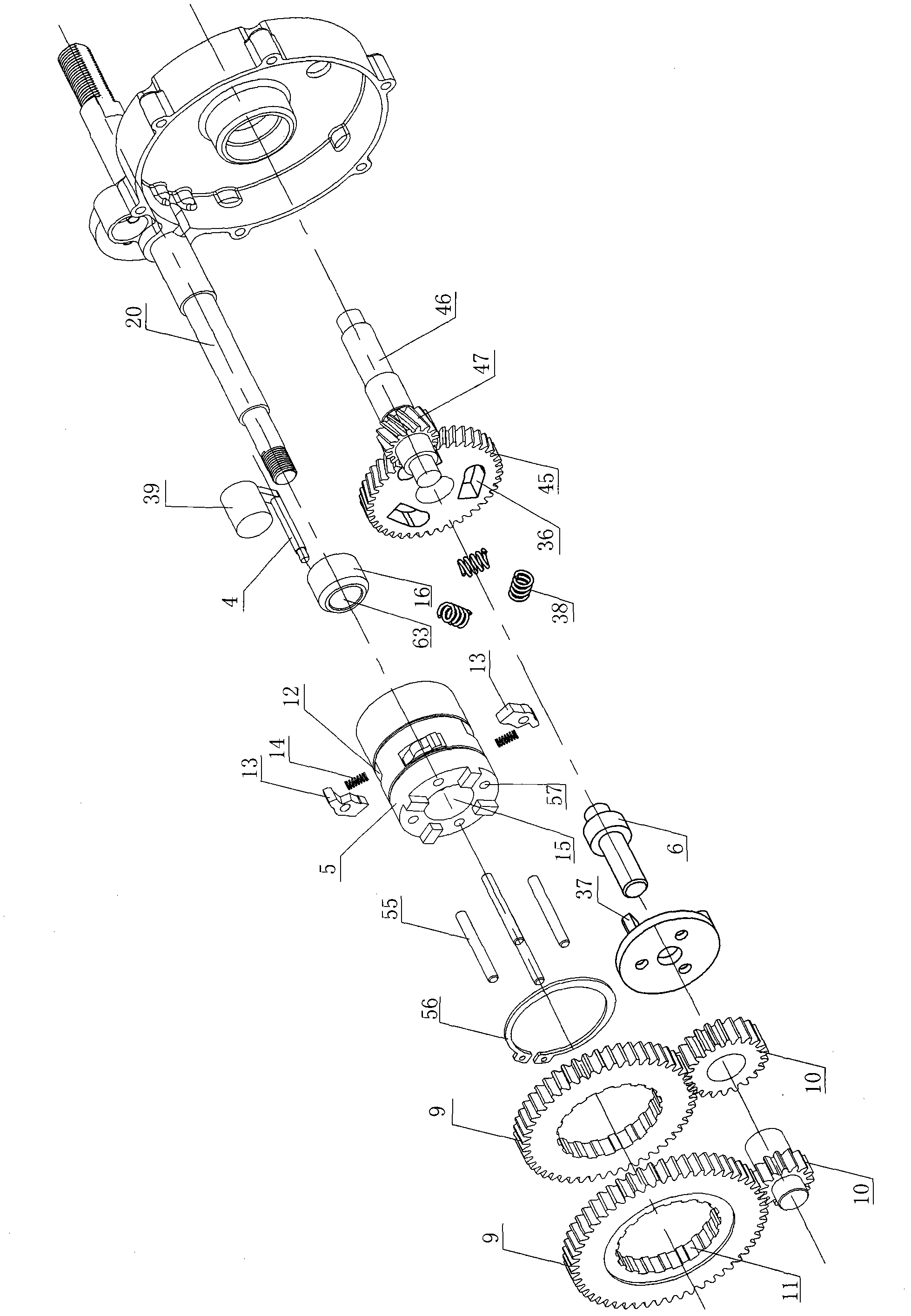
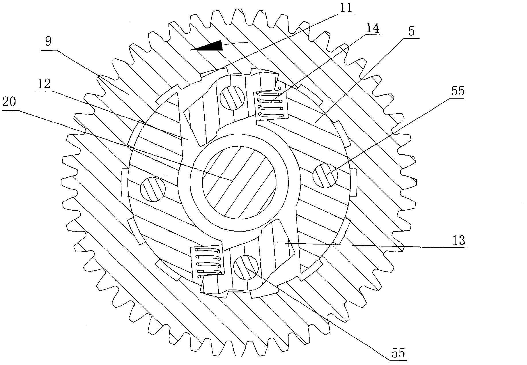
[0022] Such as figure 1 As shown, the variable speed hub motor includes a hub ring 1 connected to an end face 2 connected to a hollow output shaft 5 , and a solid support shaft 20 is provided in the shaft hole 15 of the hollow output shaft 5 .

[0023] The motor 3 is fixed on the support shaft 20, and the power cord 59 of the motor 3 protrudes from the motor casing. The motor 3 is fixed on the side of the support shaft 20, and the adjusting rod 4 and the axis line of the support shaft 20 are staggered and arranged in parallel. The motor 3 is provided with a motor shaft bearing 41 , and the motor shaft 46 is arranged in the motor shaft bearing 41 . The outer end of the motor shaft 46 is provided with a motor shaft gear 47 .

[0024] The motor 3 is fixed with a gearbox housing 21, the housing 21 is provided with a hollow output shaft 5 and an input shaft 6, the support shaft 20 passes through the shaft hole 15, and the hollow output shaft 5 is coaxial It is sleeved on the sup...


PUM


Abstract

The invention belongs to the technical field of wheels and provides a variable-speed hub motor which solves the problems that an original supporting shaft is provided with a guiding groove, an adjusting rod hole and a power line hole, and therefore the strength of the supporting shaft is lowered, the supporting shaft is prone to deformation and breakage, driving safety is affected, and heat of a motor wrapped by a hub ring can not be dissipated effectively. The variable-speed hub motor comprises a hub ring which is connected with an end face, the end face is connected with a hollow output shaft, a motor body is fixed on a supporting shaft, a power line of the motor body directly stretches out of a motor shell, and the motor body and a gearbox body are exposed out of the end face. The variable-speed hub motor is characterized in that the supporting shaft and a motor shaft are parallel, a driven gear is provided with inner teeth, the hollow output shaft is provided with a pawl moving groove, a pawl shaft penetrates through a pawl arranged in the pawl moving groove, the pawl can tilt in the pawl moving groove, and the pawl moving groove is provided with a pressure spring enabling one end of the pawl to tilt and to be clamped on the inner teeth.

Description

technical field [0001] The invention belongs to the technical field of wheels. Background technique [0002] A motor and a gearbox body are wrapped in the usual speed-changing hub ring, and the motor is fixed with a hollow support shaft stretching out from the two end faces of the hub ring. The hollow support shaft of the wheel hub of this structure increases the difficulty of processing and greatly weakens the rigidity and strength of the support shaft due to the adjustment rod hole, guide groove and power cord hole. cause a threat to driving safety. In addition, because the motor is wrapped by the hub ring, the heat emitted by the motor during operation cannot be effectively dissipated, and the motor and components are easily burned due to overheating. Contents of the invention [0003] In order to solve the above-mentioned deficiencies, the object of the present invention is to provide a support shaft with high rigidity and strength, which is not easy to be twisted, d...

Claims


Application Information

Patent Timeline
Patent Type & Authority Applications(China)
IPC IPC(8): H02K7/116
Inventor 蔡贵席
Owner 蔡旭阳
Why Eureka
Try Eureka