An infinite impulse response microwave photonic filter and filtering method

An infinite impulse response and microwave photon filtering technology, applied in the field of signal processing, can solve the problems of small side mode suppression ratio, large monochromatic coherence length, limiting the sampling interval of IIR microwave photon filter, etc., to improve main and side lobe suppression Ratio, large sampling value, and the effect of optimizing features

Active Publication Date: 2017-03-01
JINAN UNIVERSITY
View PDF6 Cites 0 Cited by
  • Summary
  • Abstract
  • Description
  • Claims
  • Application Information

AI Technical Summary

Problems solved by technology

[0005] The first one: use a single-frequency laser as the light source. Take a microwave photon filter with a distributed feedback laser (DFB) as the light source as an example. The DFB light source is characterized by good monochromaticity and large coherence length. If the fiber ring length is less than the light source coherence length, the carrier will be coherent in the optical fiber ring, and filtering cannot be effectively realized. In order to avoid the carrier coherence provided by the light source, the length of the fiber ring must be greater than the coherent length of the light source, which limits the sampling interval of the IIR microwave photon filter, and cannot obtain a larger Free Spectral Range (FSR)
[0006] The second type: use a filter to filter out a part of spontaneous emission (ASE) as a microwave photon filter as a light source. The ASE light source itself is limited by the filter, and the side mode suppression ratio (SMSR) is small, resulting in the main side lobe suppression of the microwave photon filter. ratio (MSSR) is limited

Method used


Image

  • An infinite impulse response microwave photonic filter and filtering method
  • An infinite impulse response microwave photonic filter and filtering method
  • An infinite impulse response microwave photonic filter and filtering method

Examples


Embodiment Construction

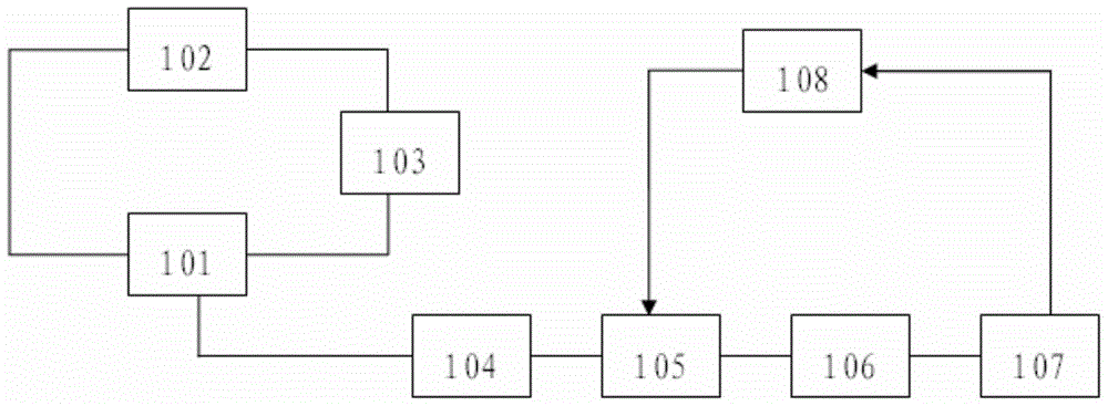
[0044] like figure 1 , 2 , 3, an infinite impulse response microwave photonic filter, such as figure 1 include:

[0045] The multi-longitudinal-mode fiber laser, as a light source, outputs stable continuous light as an optical carrier, and the optical carrier then enters the polarization controller. The multi-longitudinal-mode fiber laser includes a ring resonator composed of an optical fiber and an optical coupler 101. In the ring resonator The optical fiber amplifier 102 and the tunable optical filter 103 are connected in series, wherein the coupling ratio of the optical coupler 101 is 80:20, and the optical fiber amplifier 102 connected in series in the ring resonant cavity is used as a gain medium, working in the C-band, and its gain spectrum covers 1526nm~1566nm , since the adjustable range of the tunable optical filter 103 is greater than the working bandwidth of the fiber amplifier 102, the adjustable range of the multi-longitudinal mode fiber laser is mainly limited ...


PUM


Abstract

The invention discloses an infinite impulse response microwave photon filter and a filtering method. The infinite impulse response microwave photon filter comprises a multi-longitudinal mode fiber laser used as a light source to provide a light carrier, a polarization controller, an intensity modulator, a fiber loop and a photoelectric detector. The polarization controller regulates the polarization state of the light carrier to enable the light carrier to enter the intensity modulator, the intensity modulator works on a linear region by regulating the polarization voltage of the intensity modulator, microwave signals are modulated to the light carrier, optical signals achieve light splitting at the fiber loop, multi times of delaying and sampling are achieved on the light carrier bearing the microwave signals, the microwave signals with specific frequency are filtered, and the photoelectric detector detects the microwave signals through photovoltaic conversion to filter the light carrier. According to the filter and the filtering method, a large Q value can be provided, and a large free spectrum range is achieved due to the fact that the fiber loop can be very short.

Description

technical field [0001] The invention relates to signal processing technology, in particular to an infinite impulse response microwave photon filter and a filtering method. Background technique [0002] Filters are often used in signal processing. Compared with traditional filters, microwave photonic filters have many advantages: small loss, large bandwidth, anti-electromagnetic interference, and can provide short delays to generate ultra-high-speed sampling frequencies, which are often greater than 100GHZ, while electronic The sampling frequency of the technology can only reach a few GHZ; at the same time, microwave photonic filters also have functions such as bandwidth tunable and reconfigurable, which are difficult to achieve in traditional filters. Therefore, microwave photonic filters are more widely used. [0003] Microwave photon filters can be divided into finite impulse response (FIR) microwave photon filters and infinite impulse response (IIR) microwave photon fil...

Claims


Application Information

Patent Timeline
Patent Type & Authority Patents(China)
IPC IPC(8): H04B10/70
Inventor 冯新焕金岩冰曹元
Owner JINAN UNIVERSITY
Why Eureka
Try Eureka